Display control assembly for microwave oven door, microwave oven door and microwave oven
A technology for display and control components and microwave ovens, which is applied in the field of microwave ovens, and can solve problems such as easy dust ingress in display panels, easy damage to touch panels, and difficulty in repairing, etc., and achieves the effects of enhanced convenience, strong promotion, and low implementation difficulty
- Summary
- Abstract
- Description
- Claims
- Application Information
AI Technical Summary
Problems solved by technology
Method used
Image
Examples
Embodiment 1
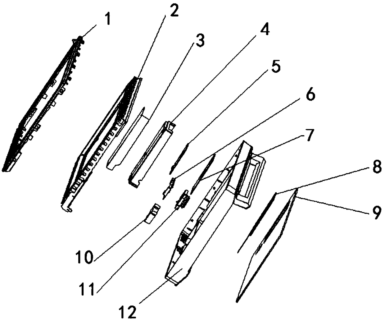
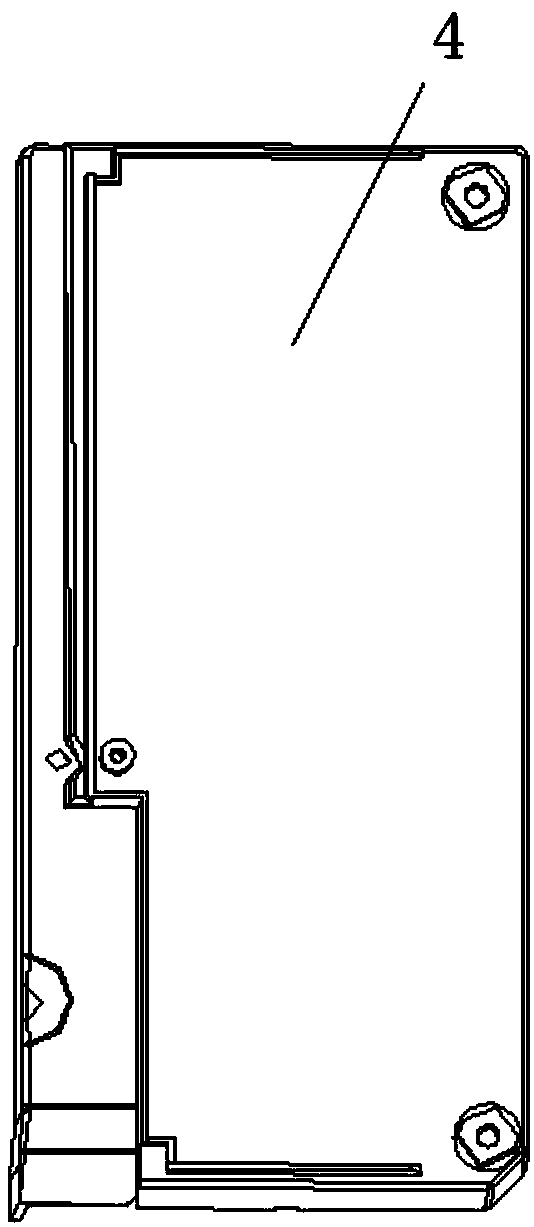
[0053] The present invention provides a display and control assembly, which includes a housing, a touch panel 8 , a display panel 7 and a computer board 5 arranged inside the housing, and the touch panel 8 and the display panel 7 are electrically connected to the computer board 5 . The display control assembly 13 of the present invention integrates the touch panel 8, the display panel 7 and the computer panel 5 into one module for installation, and changes the split installation mode into an integrated installation mode, which greatly improves the assembly efficiency of the production line, and at the same time The problem of fragility in the installation process of the display panel 7 and the touch panel 8 is solved, and once the touch display function is found to be invalid, the display and control components can be replaced in time, which enhances the convenience of repair. Such as Figure 5 As shown, the housing is composed of a base plate 15 and an outer cover 16, the bas...
Embodiment 2
[0056] The present invention also provides a display and control assembly. On the basis of Embodiment 1, the wire limiter is replaced by a cable management groove 19 connected to the outer surface of the bottom plate 15 (such as Figure 8 shown). Described wiring groove 19 can be the back-shaped groove that opening faces away from base plate 15 one side, the depth and the width of described back-shaped groove are all suitable with electric wire, and the starting end and the end end of described back-shaped groove are respectively connected with display. The outlet end of the control assembly 13 corresponds to the inlet end of the drive board 6. It can also be a plurality of bar-shaped grooves with both ends open. When in use, the wires between the display and control assembly 13 and the drive board 6 can be arranged in a spiral groove or a strip groove, so as to realize the arrangement and limit of the lead wires of the display and control assembly 13, and make reasonable use...
Embodiment 3
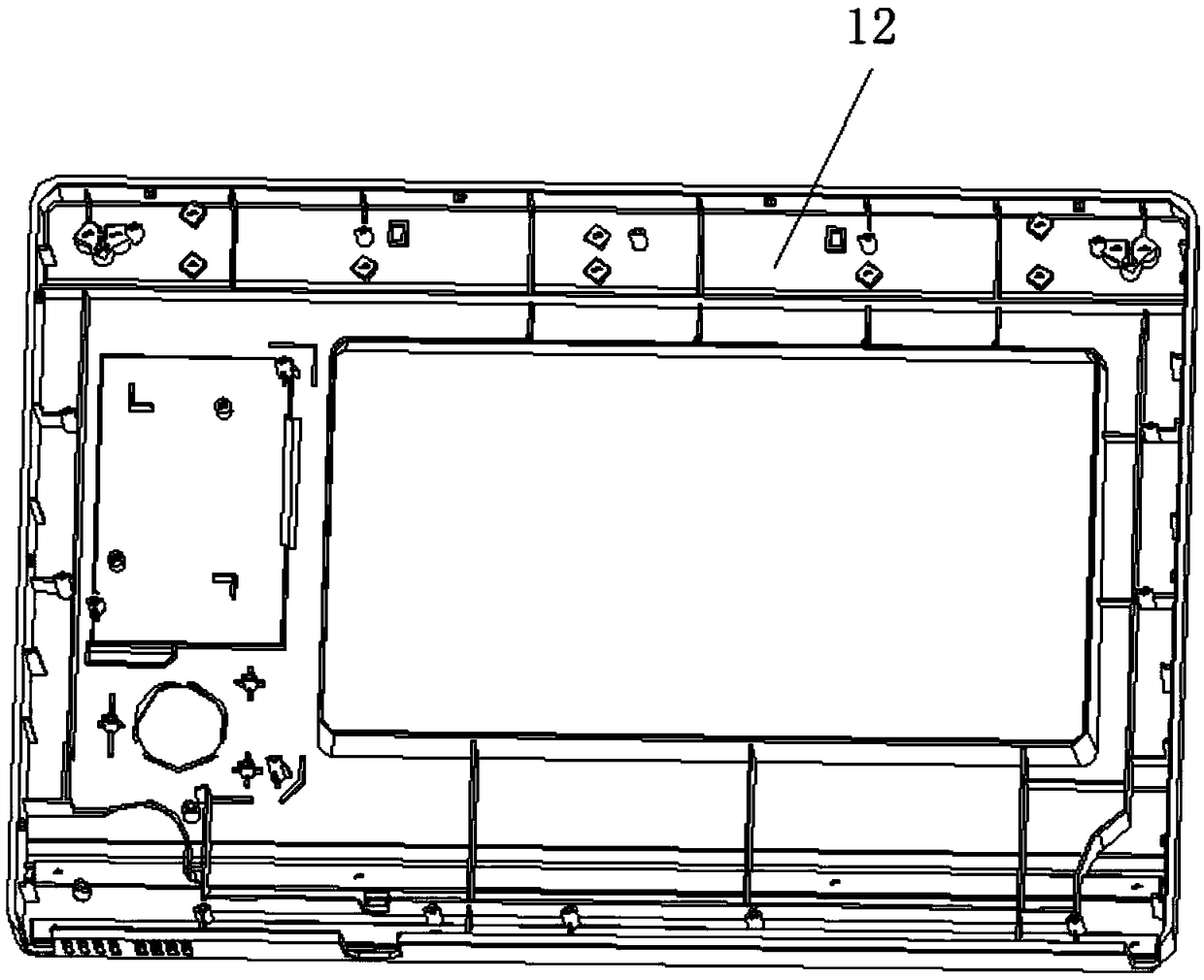
[0058] The present invention also provides a microwave oven door structure, such as Figure 6 As shown, it includes a door surface 12, a gland 18, a door body 2 and a door seal 1. The door surface 12 is provided with a square groove 121 for installing a display and control assembly 13, and the display and control assembly 13 is connected to the square At the groove 121, one end of the display control assembly 13 is connected with the knob assembly 11 and the drive board 6, the drive board 6 is electrically connected with the computer board 5, the display board 7 and the computer board 8, and one side of the drive board 6 is connected to a useful For the heat dissipation fan 10, the gland is sleeved on the outside of the display assembly and the drive board. The gland 18 is a half-shell shape with one end open. The edge of the gland is connected with the door surface 12 to form a In the accommodating space, the driving board 6 , the computer board 5 , the display board 7 , the ...
PUM
 Abstract
Description
Claims
Application Information
 - R&D
- Intellectual Property
- Life Sciences
- Materials
- Tech Scout
- Unparalleled Data Quality
- Higher Quality Content
- 60% Fewer Hallucinations
Browse by: Latest US Patents, China's latest patents, Technical Efficacy Thesaurus, Application Domain, Technology Topic, Popular Technical Reports.
© 2025 PatSnap. All rights reserved.Legal|Privacy policy|Modern Slavery Act Transparency Statement|Sitemap|About US| Contact US: help@patsnap.com


