Moving water ejection ice cutting device and ice cutting method

A water jet, horizontal technology, used in the manufacture of ice, ice storage/distribution, lighting and heating equipment, etc., can solve the problems of low degree of mechanization, high ice breaking rate, low ice breaking rate, etc., to achieve high degree of mechanization, ice breaking rate Low, reduce the effect of ice crushing rate

Active Publication Date: 2021-07-20
HARBIN UNIV OF COMMERCE
View PDF6 Cites 0 Cited by
  • Summary
  • Abstract
  • Description
  • Claims
  • Application Information

AI Technical Summary

Problems solved by technology

[0003] The purpose of the present invention is to solve the problems of low mechanization, high cost and high ice-breaking rate of existing ice-cutting devices, and provide a movable water-jet ice-cutting device and ice-cutting method with low ice-breaking rate and saving financial and material resources

Method used


Image

  • Moving water ejection ice cutting device and ice cutting method
  • Moving water ejection ice cutting device and ice cutting method
  • Moving water ejection ice cutting device and ice cutting method

Examples


Embodiment 1

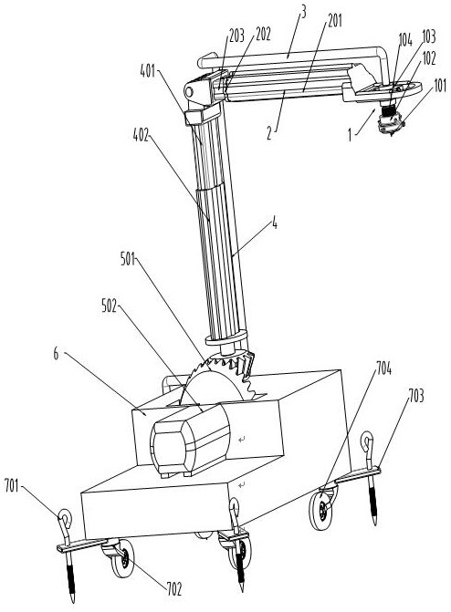
[0031] A movable water jet ice cutting device, which consists of: a base 6, a rotating part 501, a horizontal telescopic arm 2, a vertical telescopic arm 4, a nozzle 1, a main water pipe 3, and a servo motor 502. The rotary part 501, the main helical gear 5012 on the rotary part meshes with the secondary helical gear on the vertical telescopic arm 4, the vertical inner shaft 401 on the vertical telescopic arm and the vertical telescopic arm The horizontal inner shaft 203 on the horizontal telescopic arm 2 is connected by bolts, the servo motor 502 is connected to the main helical gear by a flat key, and the nozzle 1 is arranged at the end of the horizontal telescopic arm.

Embodiment 2

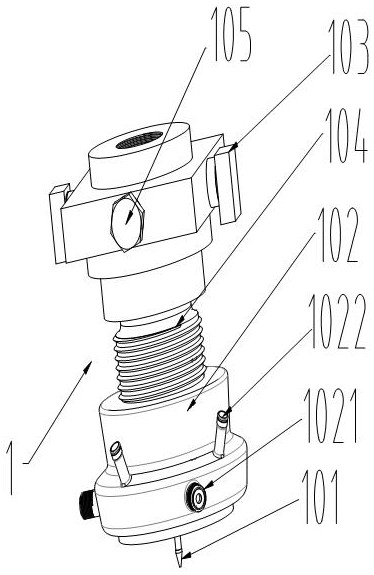
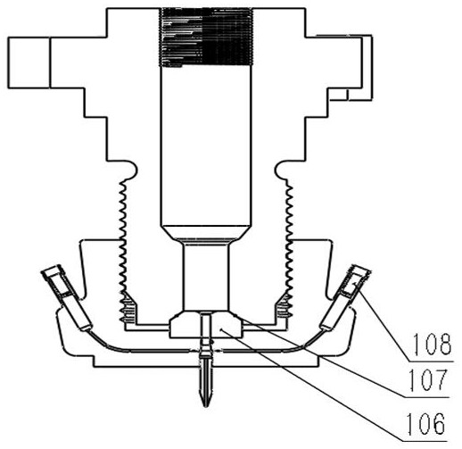
[0033] According to the movable water jet ice cutting device described in Embodiment 1, the nozzle includes a nozzle housing 104, a nozzle inner housing 102, a guide nozzle 101, an embedded block 106, and a sealing ring 107, and the nozzle housing 104 and the The nozzle inner shell 102 and the guide nozzle 101 are respectively threaded, and the nozzle inner shell 102 and the nozzle outer shell 104 are provided with an embedded block 106 and a sealing ring 107 to ensure good airtightness of the water jet. The nozzle casing 104 is provided with an auxiliary interface 1021 and a diameter-regulating flow pipe 1022, and the cavity 109 of the nozzle casing is provided with an auxiliary water pipe head 110 connected with the water pipe head through a screw thread to replenish water and necessary abrasives to To improve the cutting efficiency, the diameter-regulating flow interface 108 can be connected with various pipes, and realize threaded connection with the diameter-adjusting flow...

Embodiment 3

[0035] According to the movable water jet ice cutting device described in Embodiment 1 or 2, the horizontal telescopic arm includes a horizontal hollow shaft 201, a stopper part 202, a horizontal inner shaft 203, a hydraulic cylinder 204, spherical rollers 205, and a moving bracket 206 , spherical rollers 205 and moving brackets 206 are arranged in the cavity between the horizontal hollow shaft 201 and the horizontal inner shaft 203, and the contact surface between the horizontal hollow shaft 201 and the stop member 202 is provided with The wedge 2071 is stuck in the hollow groove on the horizontal hollow shaft 201. The bottom of the horizontal inner shaft 203 is provided with a hydraulic cylinder 204. The hydraulic cylinder is designed as a three-stage telescopic structure, which is more compact and durable. The hydraulic cylinder 204 Only simple structural designs are provided.


PUM


Abstract

The movable water jet ice-cutting device and ice-cutting method still do not have a standardized ice-cutting device with a high safety factor on the market at present. The equipment used has a low degree of mechanization and a high ice crushing rate, which consumes huge manpower, material and financial resources every year. The composition of the present invention includes: a base (6), a rotating part (501), a horizontal telescopic arm (2), a vertical telescopic arm (4), a nozzle (1), a main water pipe (3), a servo motor (502), and a Set the rotary part (501), the main helical gear (5012) on the rotary part meshes with the secondary helical gear on the vertical telescopic arm (4), the vertical inner shaft (401) on the vertical telescopic arm and the horizontal telescopic arm The horizontal inner shaft (203) on (2) is connected by bolts, the servo motor (502) is connected with the main helical gear by a flat key, and the end of the horizontal telescopic arm is provided with a nozzle (1). The invention is used for cutting ice with a movable water jet.

Description

Technical field: [0001] The invention relates to an ice cutting device, in particular to a movable water jet ice cutting device and an ice cutting method. Background technique: [0002] The Northeast region, especially Harbin Ice and Snow World, has attracted a large number of domestic and foreign tourists with its extremely cold climate and unique landscape. The ice and snow economy has also become an important boost to the economic development of the Northeast region. Ice cutters are the key to creating ice sculptures and other works of art. Basic tools, at present, there is still no standardized ice cutting device with high safety factor on the market. The equipment used has a low degree of mechanization and a high ice crushing rate, which consumes huge manpower, material resources and financial resources every year. Invention content: [0003] The purpose of the present invention is to solve the problems of low mechanization, high cost and high ice-breaking rate of exi...

Claims


Application Information

Patent Timeline
Patent Type & Authority Patents(China)
IPC IPC(8): F25C5/04
CPCF25C5/04
Inventor 金向阳薛加磊于子善
Owner HARBIN UNIV OF COMMERCE
Why Eureka
Try Eureka