Bionic mechanical leg joint driving transmission device

A bionic mechanical leg and drive transmission technology, applied in the field of bionic robots, can solve the problems of inability to meet the requirements of small volume, large load and impact resistance, increased design difficulty of bionic leg mechanism, insufficient output load force, etc., and achieve compact design of leg structure. , good terrain adaptability, the effect of saving electricity

Pending Publication Date: 2020-02-25
CHINA AIRPLANT STRENGTH RES INST
View PDF5 Cites 0 Cited by
  • Summary
  • Abstract
  • Description
  • Claims
  • Application Information

AI Technical Summary

Problems solved by technology

Since the joint driving device is embedded in the bionic leg mechanism, it will cause the design difficulty of the bionic leg mechanism to increase, the weight of the mechanism is large, and the output load capacity is insufficient. The problem of large

Method used


Image

  • Bionic mechanical leg joint driving transmission device
  • Bionic mechanical leg joint driving transmission device
  • Bionic mechanical leg joint driving transmission device

Examples


Embodiment Construction

[0030] The specific implementation manner of the present invention will be described in detail in conjunction with the summary of the invention and the accompanying drawings.

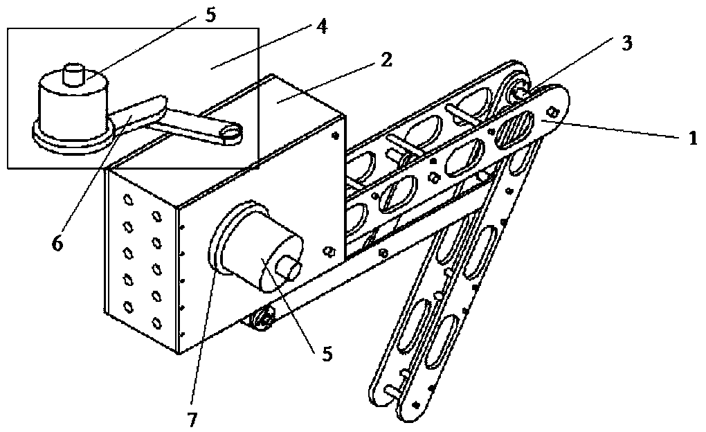
[0031] Such as figure 2 As shown, each bionic leg mechanism 1 has three bionic leg joints 3 of the base joint, the femoral joint and the tibial joint, and each bionic leg joint 3 is equipped with a joint drive transmission device 4 of the present invention to realize the independent operation of each joint. drive and control.

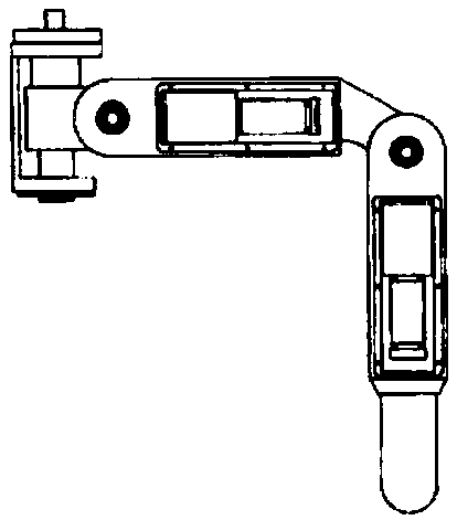
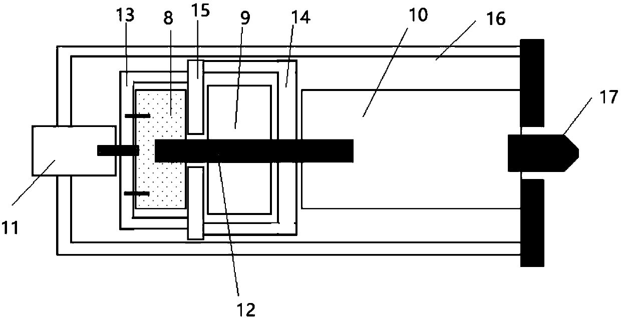
[0032] A bionic mechanical leg joint drive transmission device, including a sequentially connected drive unit assembly 5, a power output shaft 17, a transmission rod 6, and a joint control system; the power output shaft 17 and transmission rod 6 output power from the drive unit assembly passed to the joint control system.

[0033] The transmission rod 6 adopts a multi-link mechanism, and the rotating parts of the multi-link mechanism are connected by bearings.

[0034] Such a...


PUM


Abstract

The invention discloses a bionic mechanical leg joint driving transmission device. The bionic mechanical leg joint driving transmission device comprises a driving unit component, a power output shaft,a transmission rod and a joint control system which are connected in sequence. The power output shaft and the transmission rod transmit power output by the driving unit component to the joint controlsystem. According to the bionic mechanical leg joint driving transmission device, a multi-linkage mechanism is adopted for transmission, torque output by the driving unit is transmitted to a joint through the multi-linkage mechanism to achieve driving of the joint, and the bionic mechanical leg joint driving transmission device has the advantages of being small in size and large in bearing forceand also ensures the compactness and attractiveness of the leg structure.

Description

technical field [0001] The invention belongs to the field of bionic robots, and more specifically relates to a leg joint driving and transmission device of a bionic mechanical leg. Background technique [0002] At this stage, bionic robots have become one of the most active research fields. According to the different forms of motion, the structure of bionic robots can be divided into three types: wheeled, crawler and legged. Compared with wheel structure and crawler structure, legged structure robots have better environmental adaptability. Robots with bionic mechanical legs can move on rough terrain such as potholes, gravel, sand, grass, etc., and have important applications in material handling and combat assistance, and have broad application prospects. [0003] In addition, the form of bionic mechanical legs can also be applied to helicopter leg landing gear. Compared with the limitations of the two conventional landing gears of skid type and wheel type, the landing gear...

Claims


Application Information

Patent Timeline
IPC IPC(8): B25J9/00B25J9/10B25J17/00B25J19/00B62D57/02
CPCB25J9/0006B25J9/10B25J17/00B25J19/00B62D57/02
Inventor 任佳刘小川王计真牟让科
Owner CHINA AIRPLANT STRENGTH RES INST
Why Eureka
Try Eureka