sensor

A sensor and sensing surface technology, applied in the field of sensors, can solve problems such as inability to absorb objects, and achieve the effect of improving elasticity and accuracy

Active Publication Date: 2020-10-16
KITA SENSOR TECH
View PDF13 Cites 0 Cited by
  • Summary
  • Abstract
  • Description
  • Claims
  • Application Information

AI Technical Summary

Problems solved by technology

[0006] When the negative pressure source of the transfer mechanism fails and cannot function normally, the vacuum nozzle cannot suck the object
At this time, since the flow sensor senses that there is no air flow in the air pipe, the switch output of the flow sensor will still display the ON state, causing the user to mistakenly judge that the vacuum nozzle has sucked the object due to the display state of the flow sensor situation arises

Method used


Image

  • sensor
  • sensor
  • sensor

Examples


no. 1 example

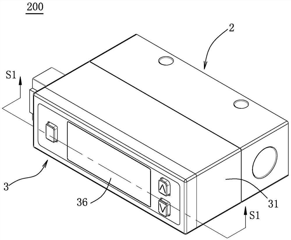
[0043] refer to image 3 , is the first embodiment of the sensor of the present invention, and the sensor 200 is an example of a flow and pressure sensor, which has the function of sensing air flow and pressure. The sensor 200 includes a flow guide housing 2 and a sensing device 3 .

[0044] refer to image 3 , Figure 4 and Figure 5 , the flow guide housing 2 includes a front end surface 21 and two side surfaces 22 , 23 respectively located on the left and right sides of the front end surface 21 . The flow guide housing 2 defines a gas flow path 24, the gas flow path 24 has a first flow path 241, a second flow path 242, a guiding flow path 243, a first guiding flow path 244, a second guiding flow path A flow path 245 , a branch flow path 246 , and a diversion hole 247 . The first flow path 241 is formed on the side surface 22 for inserting an air inlet pipe (not shown in the figure), so that the air inlet pipe can deliver the gas flow into the gas flow path 24 through t...

no. 3 example

[0064] refer to Figure 13 , is the third embodiment of the sensor of the present invention. The overall structure and sensing principle of the sensor 200 are roughly the same as those of the first embodiment, except for the location of the through hole 333 and the pressure sensing chip 324 .

[0065] In this embodiment, the through hole 333 communicates with the first conduction flow path 244 of the flow guide housing 2 , and the pressure sensing chip 324 is aligned with the through hole 333 and closes the through hole 333 . In this way, the pressure sensing chip 324 can sense the pressure of the airflow flowing into the through hole 333 through the first conduction flow path 244 .

[0066] refer to Figure 14 , is the fourth embodiment of the sensor of the present invention. The overall structure and sensing principle of the sensor 200 are roughly the same as those of the first embodiment, except for the location of the pressure sensing chip 324 .

[0067] In this embodime...


PUM


Abstract

Disclosed is a sensor, comprising a guide shell and a sensing device, wherein a gas channel is defined by the guide shell and used for guiding gas flow to flow along a first flow direction; the sensing device is arranged in the guide shell and comprises a sensing module comprising a sensing circuit board, a flow quantity sensing chip and a plurality of first guide elements; the sensing circuit board is provided with a first face facing the gas channel; the flow quantity sensing chip is arranged on the first face for sensing the quantity of gas flow flowing through the gas channel; the flow quantity sensing chip is provided with a sensing face provided with a first side edge; the first guide elements are convexly arranged on the first face and spaced with the first side edge; the first guide elements are in long strip shapes and extend along the first flow direction and used for rectifying the gas flow to enable the rectified gas flow to flow through the sensing face.

Description

technical field [0001] The invention relates to a sensor, in particular to a sensor for sensing air flow. Background technique [0002] refer to figure 1 and figure 2 , the existing thermal mass flow sensor includes a circuit board 11 and a flow sensing chip 12 arranged on the circuit board 11 . Both the circuit board 11 and the flow sensing chip 12 are located on the gas flow path. The flow sensing chip 12 is arranged and fixed on the surface 111 of the circuit board 11 , the flow sensing chip 12 is used to heat the gas and sense the temperature of the gas before and after heating, and calculate the gas flow by the sensed temperature difference. [0003] Since the surface 111 of the circuit board 11 is protruded with a curved conductive circuit 112 made of metal copper foil, and the extension direction of the aforementioned conductive circuit 112 is different from the flow direction of the airflow 13, therefore, the airflow 13 flows through the aforementioned conductive...

Claims


Application Information

Patent Timeline
Patent Type & Authority Patents(China)
IPC IPC(8): G01F1/684G01F1/36
CPCG01F1/363G01F1/6842
Inventor 陈兆麟真绪明伦
Owner KITA SENSOR TECH
Why Eureka
Try Eureka