Joint bearing testing device

A joint bearing and test device technology, which is applied in the direction of mechanical bearing testing, etc., can solve the problems of low service life of rolling bearings, low mandrel life, and force bending, etc., so as to improve life, improve mandrel life, and reduce the number of replacements Effect

Pending Publication Date: 2018-12-18
FUJIAN LONGXI BEARING (GROUP) CO LTD
View PDF10 Cites 4 Cited by
  • Summary
  • Abstract
  • Description
  • Claims
  • Application Information

AI Technical Summary

Problems solved by technology

Because the life test of the joint bearing is a heavy-duty low-speed swing condition, the length of the mandrel 2' of this device is long, and it is seriously bent under force. In actual application, it often happens that the service life of the test bearing and the mandrel is lower than that of the test bearing

Method used


Image

  • Joint bearing testing device
  • Joint bearing testing device
  • Joint bearing testing device

Examples


Embodiment Construction

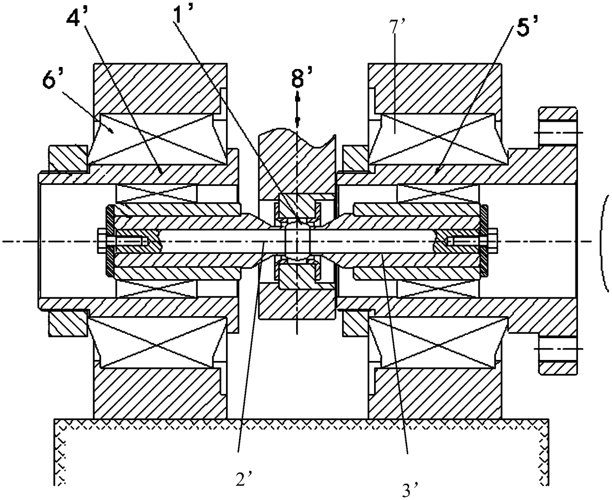
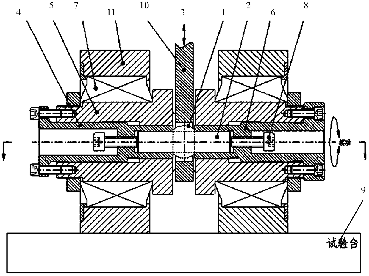
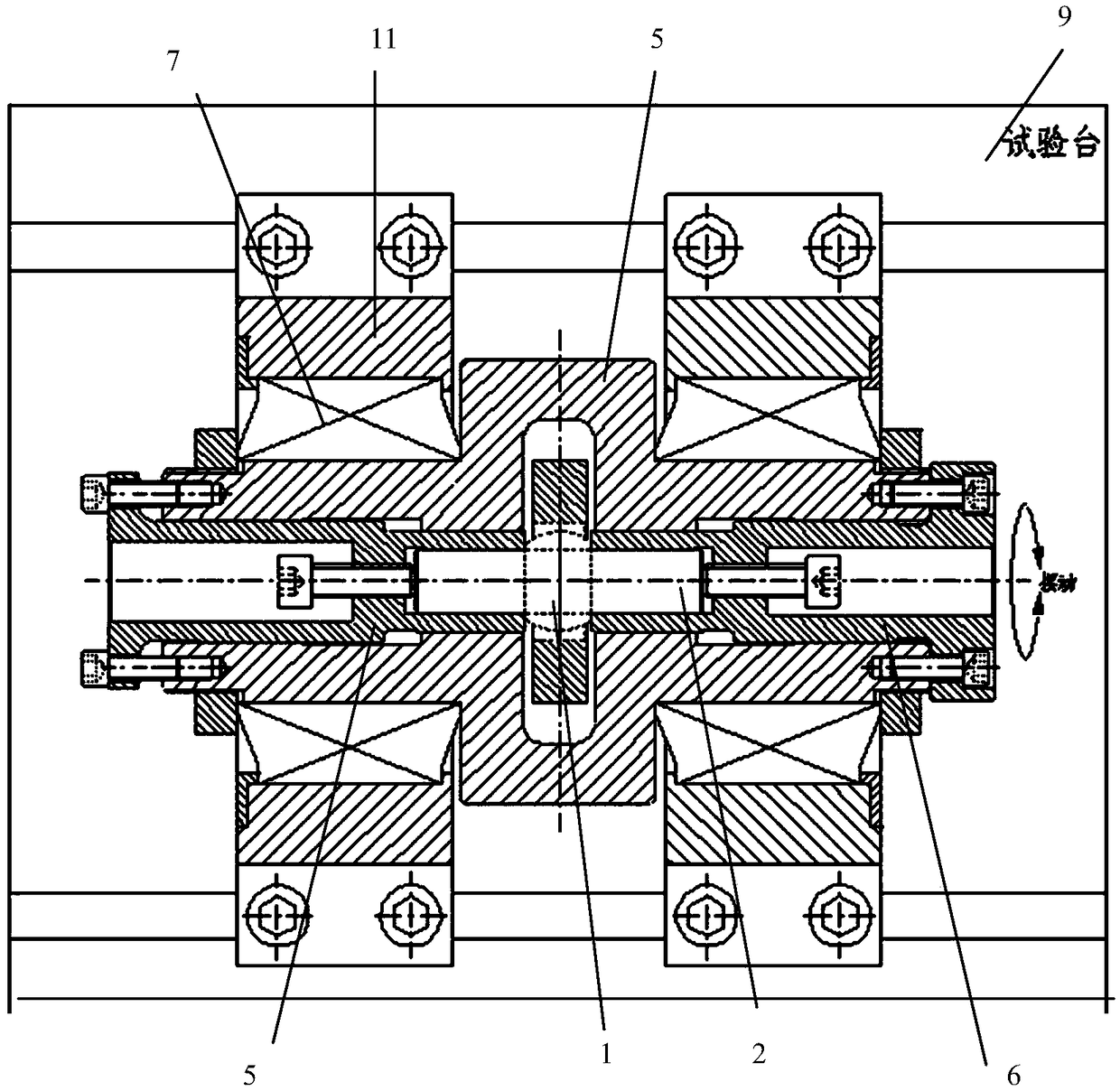
[0022] Examples, see Figure 1 to Figure 3 As shown, a joint bearing test device of the present invention includes a joint bearing 1, a mandrel 2, a load 3, a main rotating sleeve 4, a left sleeve 5, a right sleeve 6 and a rolling bearing 7; the mandrel 2 passes through In the inner ring hole of the joint bearing 1, the two ends of the mandrel 2 are respectively socketed inside the left bushing 5 and the right bushing 6, and the left bushing 5 and the right bushing 6 are respectively socketed In the main rotary sleeve 4, in this embodiment, the main rotary sleeve 4, the left and right shaft sleeves 5 and 6, and the mandrel 2 adopt interference fit or small clearance fit. The outside of the left bushing 5 and the right bushing 6 are provided with axial screw holes, and the tension screw 8 pushes the mandrel 2 inside the left bushing 5 or the right bushing 6 through the screw holes, Tighten the screw 8 to fine-tune the position and pre-tightening force; the two ends of the main...


PUM


Abstract

The invention discloses a joint bearing testing device which comprises a joint bearing, a central spindle and a load and is characterized by further comprising a main rotary liner, a left shaft sleeve, a right shaft sleeve and rolling bearings, wherein the central spindle passes through an inner ring hole of the joint bearing; both ends of the central spindle are respectively sleeved with the leftshaft sleeve and the right shaft sleeve; the left shaft sleeve and the right shaft sleeve are respectively sleeved with the main rotary liner; an axial screw hole is formed outside the left shaft sleeve or the right shaft sleeve; a tensioning screw passes through the screw hole to push the central spindle inside the left shaft sleeve or the right shaft sleeve; both ends of the main rotary liner are respectively mounted on a test stand by the rolling bearings; and the load is loaded to an outer ring of the joint bearing. According to the invention, by transition of the main rotary liner and the left and right shaft sleeves, high-rigidity supporting is provided for the central spindle, a loaded bending degree of the central spindle is minimized, a working condition is the mostly approximateto an only sheared working condition, and the service life of the central spindle is prolonged.

Description

technical field [0001] The invention relates to a joint bearing test device. Background technique [0002] The existing joint bearing life test device such as figure 1 As shown, it includes a test bearing 1', a mandrel 2', a shaft sleeve 3', a left turn sleeve 4' and a right turn sleeve 5', the mandrel 2' is sleeved in the inner ring of the test bearing 1', and the core The two sides of the shaft 2' are socketed in the shaft sleeve 3', and the two ends of the shaft sleeve 3' are respectively installed in the left rotation sleeve 4' and the right rotation sleeve 5', and the left rotation sleeve 4' and the right rotation sleeve The sleeve 5' is installed on the test bench through the test bearings 6' and 7' respectively. The device tests the life of the bearing by swinging the left rotary sleeve 4' or the right rotary sleeve 5' and applying a load 8' to the outer ring of the test bearing 1'. Because the life test of the joint bearing is a heavy-duty low-speed swing conditio...

Claims


Application Information

Patent Timeline
Patent Type & Authority Applications(China)
IPC IPC(8): G01M13/04
CPCG01M13/04
Inventor 许志宏何两加曾湘木曾春祥
Owner FUJIAN LONGXI BEARING (GROUP) CO LTD
Why Eureka
Try Eureka