Laser radar coaxial optical system and laser radar

A laser radar and optical system technology, applied in the field of artificial intelligence, can solve the problems of large size, time-consuming and laborious debugging, and large environmental impact, and achieve the effects of small size, easy installation and transportation, and less loss of optical signals

Pending Publication Date: 2018-12-18
BENEWAKE BEIJING TECH CO LTD
View PDF5 Cites 27 Cited by
  • Summary
  • Abstract
  • Description
  • Claims
  • Application Information

AI Technical Summary

Problems solved by technology

[0004] The purpose of this application is to propose a laser radar coaxial optical system and laser radar. Through the design of the coaxial optical path, the transmitted and received optical paths are combined through a perforated mirror, and then scanned by a MEMS vibrating mirror, which solves the problem of existing problems. The debugging of non-coaxial laser radar is time-consuming and laborious, and it is greatly affected by optical components and the environment, and the problem of large volume

Method used


Image

  • Laser radar coaxial optical system and laser radar
  • Laser radar coaxial optical system and laser radar
  • Laser radar coaxial optical system and laser radar

Examples


Embodiment 1

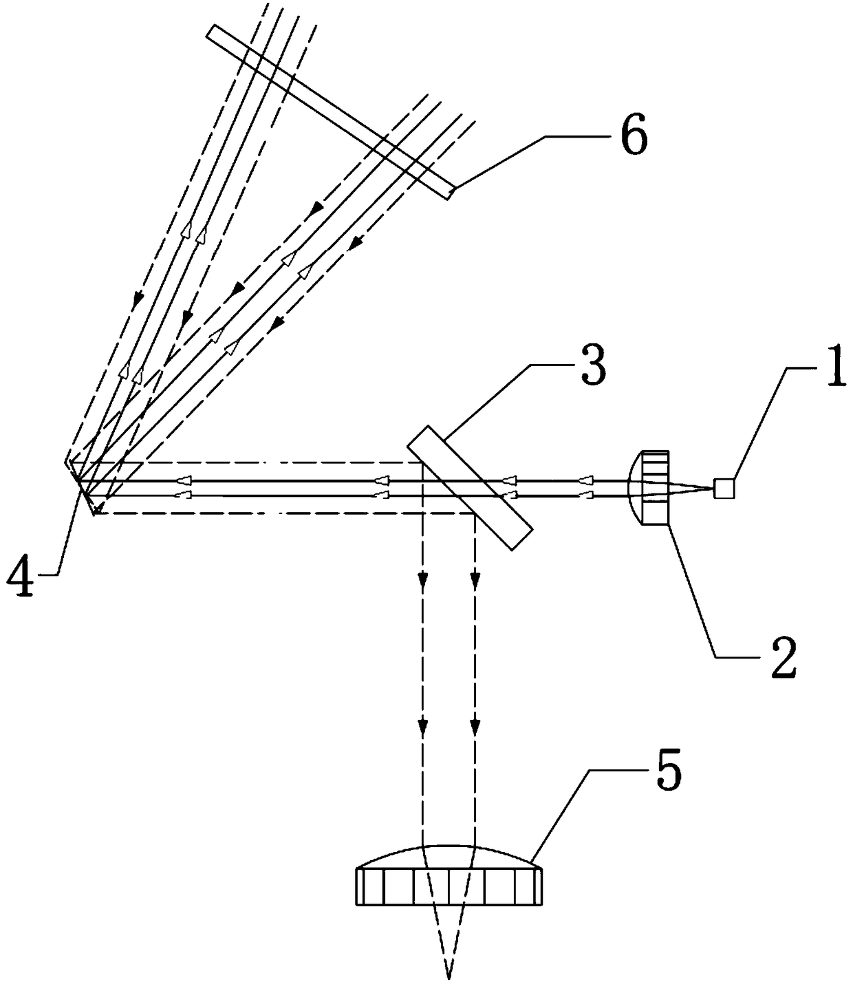
[0029] Such as figure 1 As shown, a laser radar optical system includes a transmitting optical unit and a receiving optical unit. The transmitting optical unit includes a laser 1, a collimator lens 2, and a MEMS vibrating mirror 4. The receiving optical unit includes a receiving lens 5 and a perforated mirror 3. Among them, a collimator lens 2, a perforated reflector 3, and a MEMS vibrating mirror 4 are sequentially arranged on the subsequent optical path of the laser emitting beam, and the laser emitting beam passes through the small hole of the perforated reflector 3 after being collimated by the collimating lens 2 Incident MEMS vibrating mirror 4, MEMS vibrating mirror 4 deflects and reflects the incident laser light onto the target object, and the reflected light of the target object is reflected by MEMS vibrating mirror 4 and enters the receiving optical unit.

[0030] The incident angle of the laser emitting beam incident on the MEMS vibrating mirror 4 is 25-30 degrees, ...

Embodiment 2

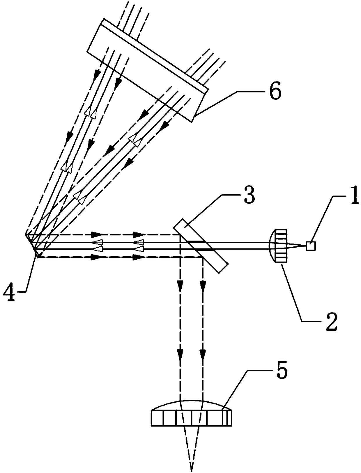
[0040] Such as figure 2 As shown, a laser radar optical system includes a transmitting optical unit and a receiving optical unit. The transmitting optical unit includes a laser 1, a collimator lens 2, and a MEMS vibrating mirror 4. The receiving optical unit includes a receiving lens 5 and a perforated mirror 3. Among them, a collimator lens 2, a perforated reflector 3, and a MEMS vibrating mirror 4 are sequentially arranged on the subsequent optical path of the laser emitting beam, and the laser emitting beam passes through the small hole of the perforated reflector 3 after being collimated by the collimating lens 2 Incident MEMS vibrating mirror 4, MEMS vibrating mirror 4 deflects and reflects the incident laser light onto the target object, and the reflected light of the target object is reflected by MEMS vibrating mirror 4 and enters the receiving optical unit.

[0041] The incident angle of the laser emitting beam incident on the MEMS vibrating mirror 4 is 26-28 degrees,...


PUM


Abstract

The invention relates to the technical field of artificial intelligence, and in particular relates to a laser radar coaxial optical system. The laser radar optical system comprises a transmitting optical unit and a receiving optical unit; the transmitting optical unit comprises a laser, a collimating lens and an MEMS galvanometer; the receiving optical unit comprises a receiving lens and an aperture reflector, wherein the collimating lens, the aperture reflector and the MEMS galvanometer are sequentially arranged on the subsequent optical path of the light beam transmitted by the laser; afterbeing collimated through the collimating lens, the light beam transmitted by the laser passes through the small hole of the aperture reflector, and enters the MEMS galvanometer; the MEMS galvanometerdeflects and reflects incidence laser onto a target object; and reflected light of the target object is reflected through the MEMS galvanometer, and enters the receiving optical unit. According to thelaser radar coaxial optical system and the laser radar in the invention, coaxial optical path design is adopted; transmitting and receiving optical paths are combined through the aperture reflector;exit laser is scanned from the combined laser through the MEMS galvanometer; the laser radar optical system is convenient to debug; furthermore, due to beam combination, optical signal loss is low; and the detection distance is greatly increased.

Description

technical field [0001] The present application relates to the technical field of artificial intelligence, in particular to a laser radar coaxial optical system and a laser radar. Background technique [0002] Lidar is an active distance detection device that uses a laser as a light source and uses photoelectric detection technology. It has the advantages of small size and high measurement accuracy, and is widely used in unmanned driving, automatic guided vehicles (Automatic Guided Vehicle, AGV), and robots. and other fields. [0003] At present, the common laser radar has a non-coaxial design for its transmitting beam and receiving beam. The laser radar beam of this design will not pose a threat to the photoelectric receiver. There are many shortcomings. First of all, in the case of non-coaxial lidar structure, in order to ensure that the transmitting beam and the receiving beam are always coaxial or parallel, it is necessary to debug the transmitting part and the receiving...

Claims


Application Information

Patent Timeline
Patent Type & Authority Applications(China)
IPC IPC(8): G01S7/481
CPCG01S7/481
Inventor 疏达李远杨野张海武贺兴华
Owner BENEWAKE BEIJING TECH CO LTD
Why Eureka
Try Eureka