

Angular velocity sensor
An angular velocity sensor and velocity technology, which can be used in instruments, gyroscopic effects for velocity measurement, velocity/acceleration/shock measurement, etc., and can solve problems such as no
- Summary
- Abstract
- Description
- Claims
- Application Information
AI Technical Summary
Problems solved by technology
Method used
Image

Examples
Embodiment 1
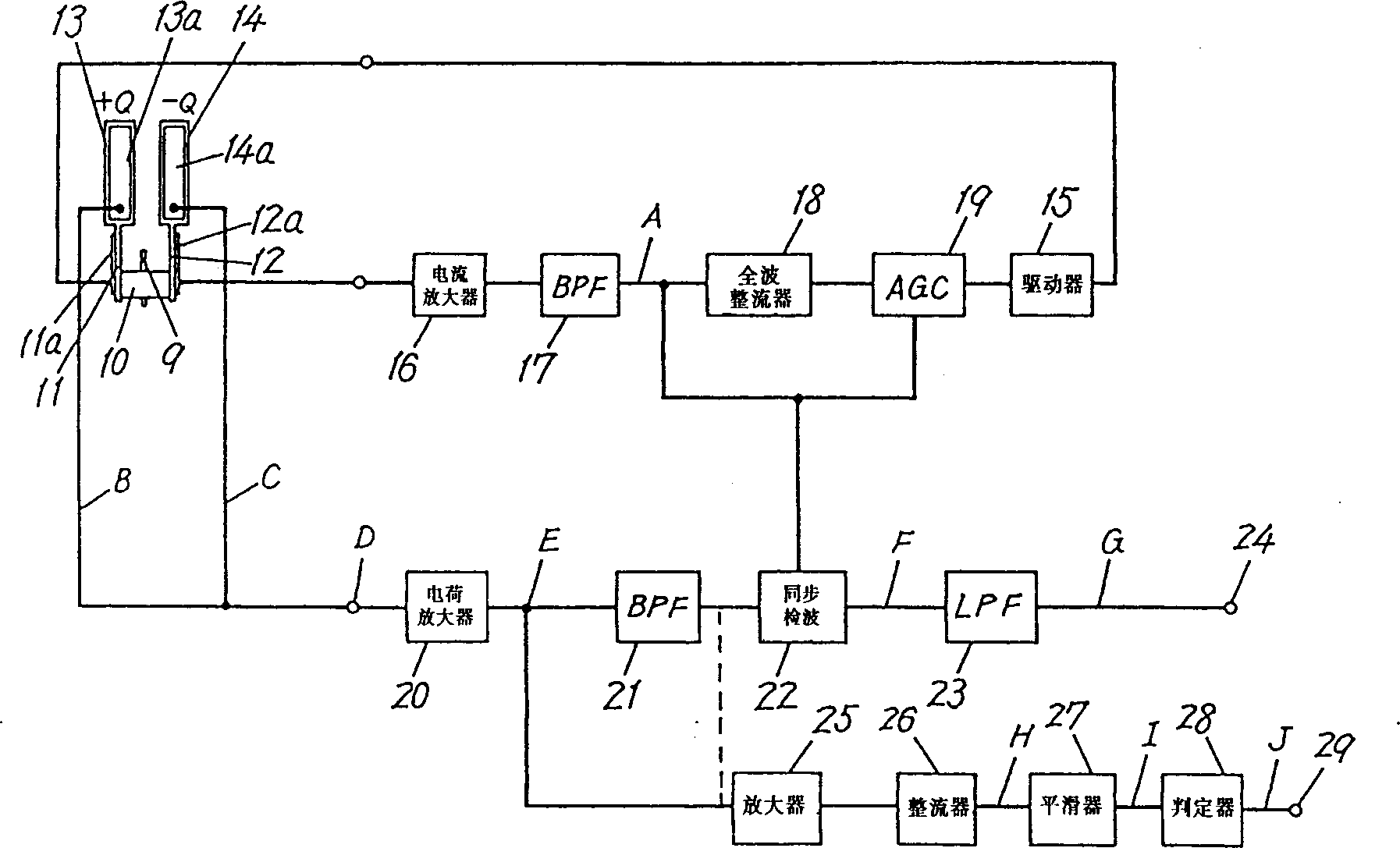
[0013] figure 1 It is a circuit diagram of the control circuit in the first embodiment of the angular velocity sensor of the present invention. The driver 15 applies a 1VP-P (peak-to-peak), 1.5KHz AC signal as a driving signal to the piezoelectric element 11a of the driving board 11 as a sensing element. As a result, the drive plates 11 and 12 begin to vibrate as a tuning fork centered on the support rod 9 in the inner and outer directions. The piezoelectric element 12a of the driving board 12 generates an induced voltage proportional to the applied signal due to the vibration of the tuning fork, and the voltage passes through the current amplifier 16 and the band-pass filter 17 to form at point A figure 2 The monitoring signal shown in A. The signal is fed back to the driver 15 through the subsequent full-wave rectifier 18 and AGC circuit 19 to perform AGC control on the driving signal. In the detection section, when the piezoelectric elements 13a and 14a detect the angu...
Embodiment 2
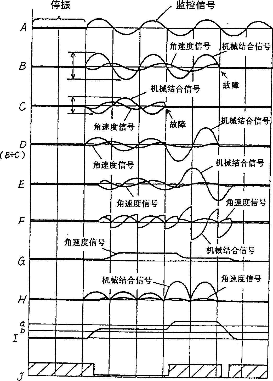
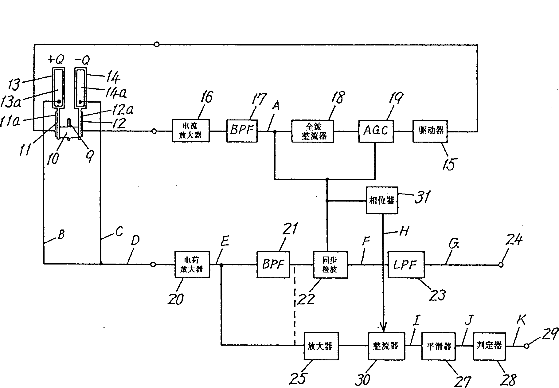
[0016] image 3 represents another embodiment, in this embodiment, the synchronous detector 30 is interposed between the amplifier 25 and the smoother 27, and uses the feedback signal of the feedback circuit in the drive signal, namely from image 3 The signal at point A passing through the phaser 31 is subjected to synchronous detection. That is, the mechanical coupling signal flowing into the amplifier 25 is also mixed with the angular velocity signal, so the angular velocity signal is canceled to bring the level of the mechanical coupling signal closer to the correct value. For this purpose, as described above, phaser 31 is used to pair the incoming image 3 in point A Figure 4 The phase shift of middle signal A lags 90°, if use Figure 4 Shown in H has the output of the amplifier 25 from the synchronous detection of the signal with this 90° lagging phase, then as Figure 4 As shown in I, the angular velocity signal is eliminated, and the level of the mechanically comb...
Embodiment 3
[0018] Figure 5 represents yet another embodiment in which the Figure 5 The middle point D is initially set to zero when adding the mechanical coupling signals obtained from the piezoelectric elements 13a and 14a. That is, in this example, for figure 1 , image 3 In the state where the sum is not zero, the balance of the detection board 13 or 14 is adjusted so that the sum of the mechanical combination signals generated by the piezoelectric elements 13a and 14a is initially set to zero. This situation is expressed in Figure 6 In D, the mechanical coupling signal does not appear in the normal state before a fault such as damage to the detection board 14 or a lead wire falling off occurs, for example. Figure 5 On point D. However, after this failure occurs, since the piezoelectric element 14a does not generate a mechanical coupling signal, as Figure 6 As shown in D, a mechanobinding signal appears. As a result, such as Figure 6 As shown in J, when a fault occurs, th...
PUM
 Abstract
Description
Claims
Application Information