Automatic positioning method and device for tips of different micro pipettes in automatic microinjection system

A technology of microinjection and automatic positioning, which is applied in the directions of image data processing, instruments, and analysis materials, etc., and can solve problems such as inability to accurately locate the needle tip position of the suction needle, separation of the injection needle from the background, etc.

Active Publication Date: 2018-12-18
HARBIN INST OF TECH
View PDF4 Cites 8 Cited by
  • Summary
  • Abstract
  • Description
  • Claims
  • Application Information

AI Technical Summary

Problems solved by technology

[0004] The purpose of the present invention is to solve the disadvantages of the existing needle point positioning method that it is difficult to separate the injection needle from the background, which leads to the i

Method used


Image

  • Automatic positioning method and device for tips of different micro pipettes in automatic microinjection system
  • Automatic positioning method and device for tips of different micro pipettes in automatic microinjection system
  • Automatic positioning method and device for tips of different micro pipettes in automatic microinjection system

Examples


specific Embodiment approach 1

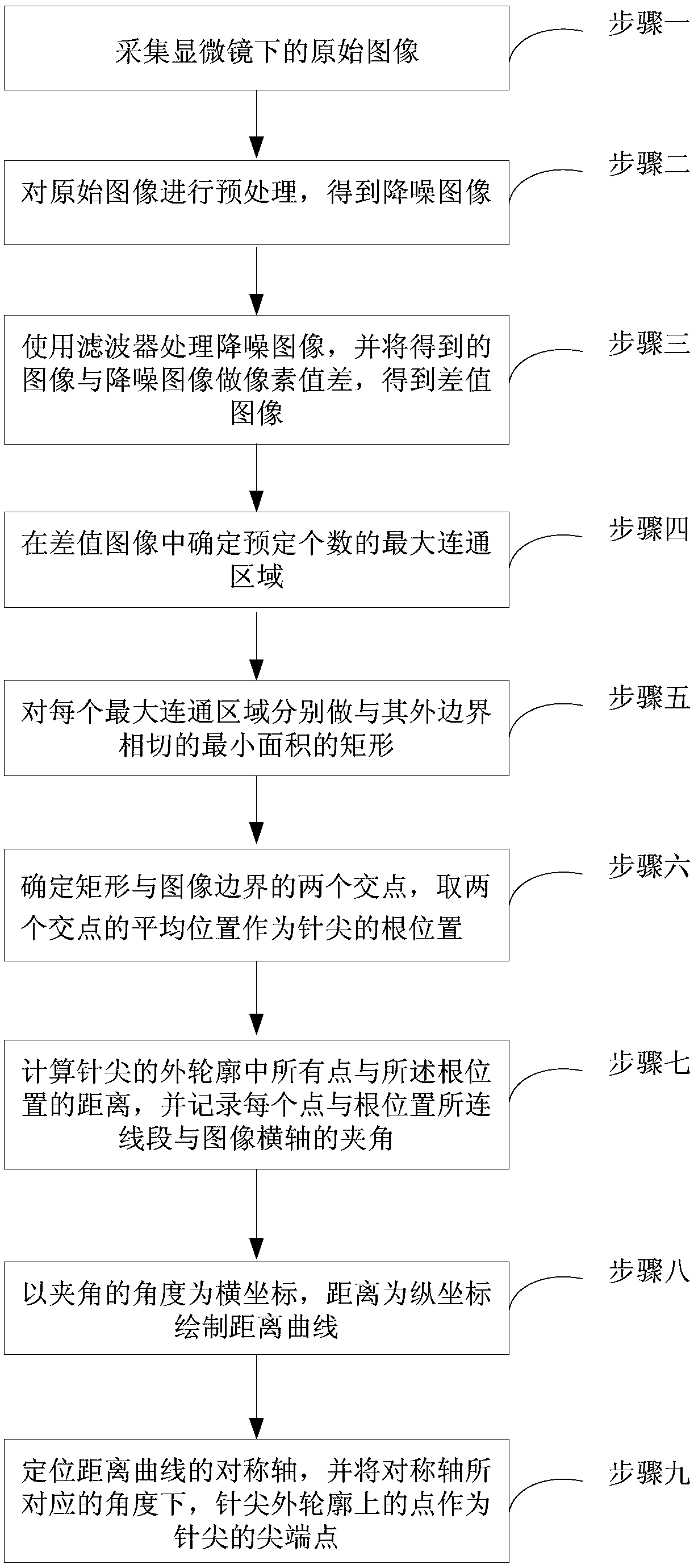
[0032] Embodiment 1: The automatic positioning method of different micropipette tips in the automatic microinjection system of the present embodiment comprises the following steps:

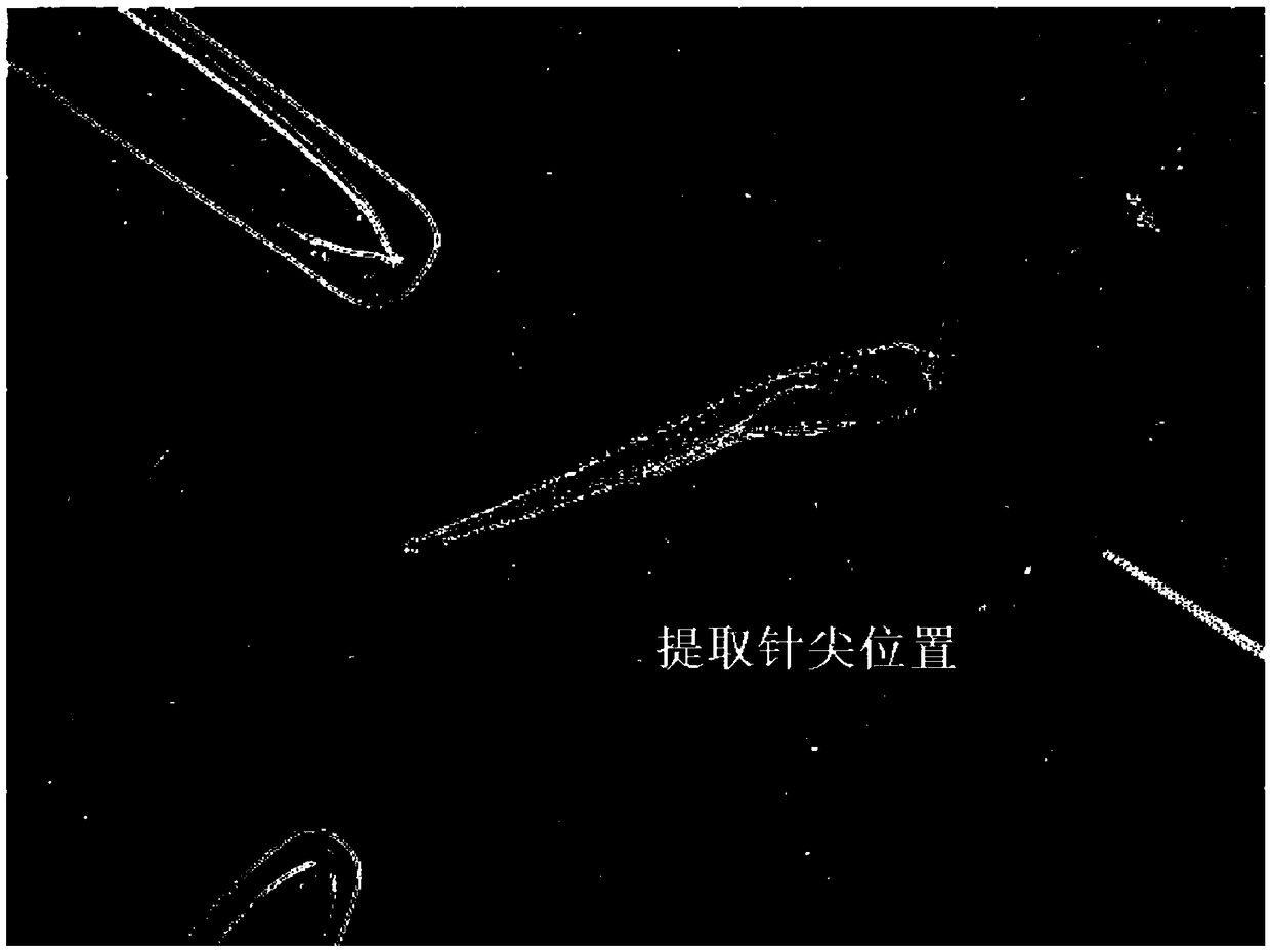
[0033] Step 1. Collect the original image under the microscope. where the original image as figure 2 shown.

[0034] Step 2. Preprocessing the original image to obtain a noise-reduced image.

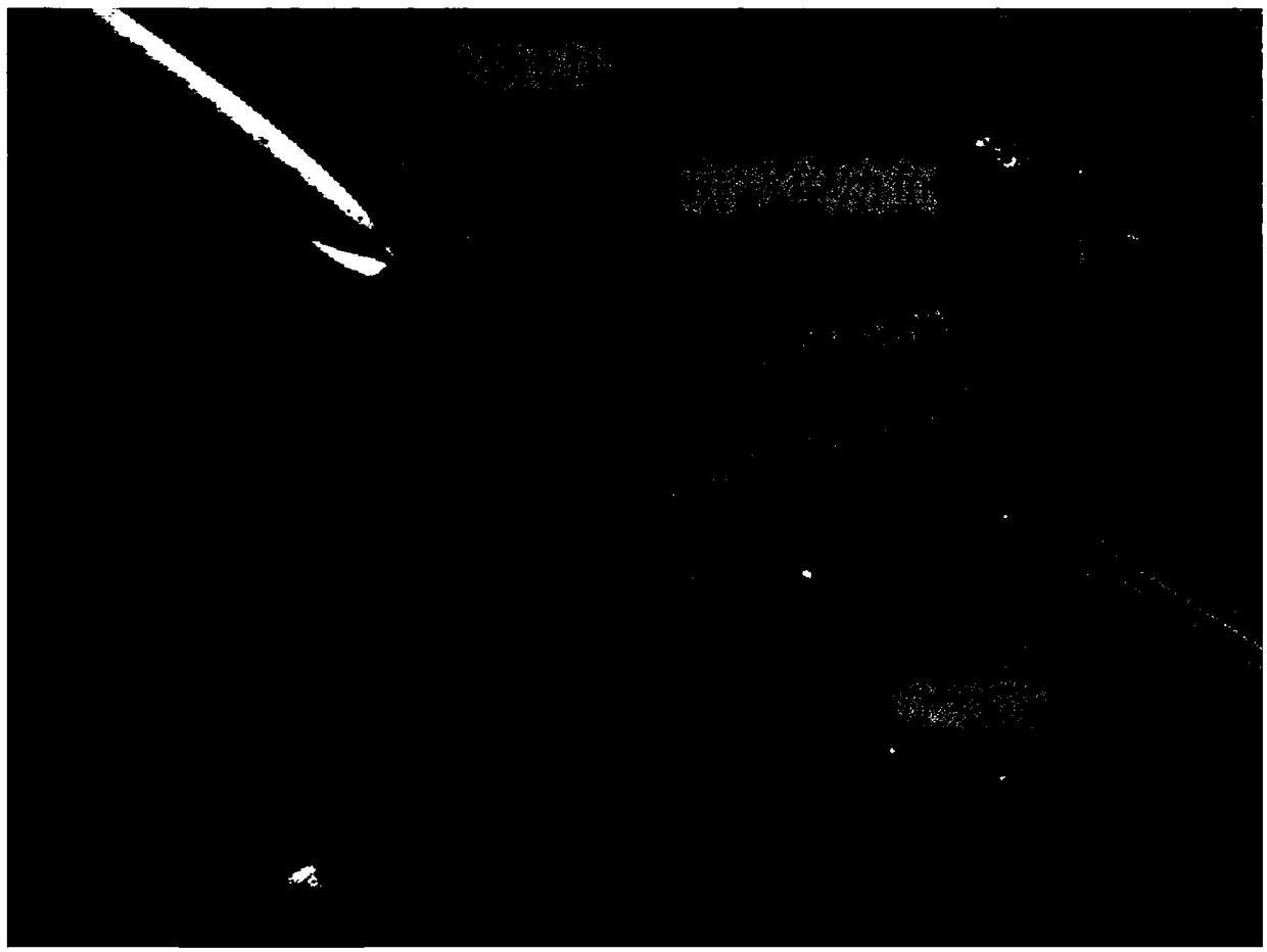
[0035] Step 3: Process the noise-reduced image with a filter, and perform pixel value difference between the obtained image and the noise-reduced image to obtain a difference image. The purpose of this step is to deepen the part of the needle tip with strong directionality, so that the background part does not change significantly, and then the approximate position of the needle tip can be obtained, such as image 3 shown.

[0036] Step 4. Determine a predetermined number of maximum connected regions in the difference image; each of the maximum connected regions is used to characterize the region where ...

specific Embodiment approach 2

[0043] Specific implementation mode two: the difference between this implementation mode and specific implementation mode one is: in step two, the preprocessing includes:

[0044] Step 2.1, reduce noise in the image through a low-pass Gaussian filter.

[0045] Step 2.2, using global binarization to remove noise caused by impurities in the petri dish in the field of view of the microscope.

[0046] Other steps and parameters are the same as those in Embodiment 1.

specific Embodiment approach 3

[0047] Specific embodiment three: the difference between this embodiment and specific embodiment one or two is:

[0048] In step 3, the filter is a Gabor filter. The Gabor filter can amplify the direction information, which is more in line with the requirements of the present invention.

[0049] Other steps and parameters are the same as those in Embodiment 1 or Embodiment 2.


PUM


Abstract

The invention relates to an automatic positioning method and a device for tips of different micro pipettes in an automatic microinjection system, belonging to the field of automatic microinjection system. The present invention provides an automatic positioning method for different micro pipette tips in an automatic microinjection system in order to solve the problem that the existing needle tip positioning method is difficult to separate the injection needle from the background, so that the needle tip position of the suction needle cannot be accurately positioned. The automatic positioning method comprises the following steps: pre-processing the acquired original image; the pixel value difference being made between the filtered image and the denoised image; determining a maximum connectingarea of a predetermined number; making the circumscribed rectangle of the connected region, and determining the average position of the intersection point of the circumscribed rectangle and the imageboundary as the root position of the needle tip; calculating the distance between all points in the outer contour and the root position, and the included angle between the line segment connected withthe root position and the horizontal axis of the image; making a distance curve to determine the position of the tip of the needle. The invention is suitable for automatic microinjection of organisms.

Description

technical field [0001] The invention relates to an automatic positioning method and device for tips of different micropipettes in an automatic microinjection system, belonging to the field of automatic microinjection systems. Background technique [0002] In biological experiments and medical research, injection technology is playing an increasingly important role, so people have begun to continuously research and explore automatic microinjection technology. In the automatic microinjection system, the image of the microscope is mainly used as the feedback signal, and the micropipette operated by the mechanical arm is used as the main body to operate the objects in the field of view. Among them, micropipettes, namely glass needles, can be divided into injection needles and suction needles due to their different shapes and uses. [0003] In the process of automatic microinjection, it is first necessary to determine the exact positions of multiple micropipettes with different ...

Claims


Application Information

Patent Timeline
IPC IPC(8): G06T7/73G06T7/194G06T7/187G06T7/11G01N35/10
CPCG01N35/10G06T7/11G06T7/187G06T7/194G06T7/73
Inventor 高会军庄松霖佟明斯林伟阳李湛
Owner HARBIN INST OF TECH
Why Eureka
Try Eureka