A rail transit vehicle

A rail transit vehicle and car body technology, applied in the field of rail transit, can solve the problems of convenience limitation, poor adaptability, hard object scratch damage and other problems in the installation and maintenance of traction transformers, so as to improve work reliability and adaptability, improve The effect of working reliability and prolonging the service life

Active Publication Date: 2018-12-18
CSR ZHUZHOU ELECTRIC CO LTD
View PDF3 Cites 0 Cited by
  • Summary
  • Abstract
  • Description
  • Claims
  • Application Information

AI Technical Summary

Problems solved by technology

[0004] However, the existing traction transformers are usually installed at the bottom of the rail transit vehicle. This arrangement requires a certain height and space at the bottom of the rail transit vehicle to accommodate the traction transformer, which limits the convenience of installation and maintenance of the traction transformer. And it is easy to be polluted and blocked by muddy water at the bottom of the vehicle, and it is also easy to be scratched and damaged by hard objects on the bottom of the vehicle, which seriously affects the service life of the traction transformer, thereby affecting the working reliability of the rail transit vehicle
In addition, due to the installation of components such as traction transformers, the height of the bottom surface of the rail vehicle from the ground is relatively high. During use, it is usually necessary to add a platform of a certain height for passengers to get on and off the train, which makes the use of the rail vehicle environment limited. poor
[0005] Therefore, the setting of the existing traction transformer makes the working reliability and adaptability of the rail transit vehicle lower

Method used


Image

  • A rail transit vehicle
  • A rail transit vehicle

Examples


Embodiment Construction

[0030] The following will clearly and completely describe the technical solutions in the embodiments of the present invention with reference to the accompanying drawings in the embodiments of the present invention. Obviously, the described embodiments are only some, not all, embodiments of the present invention. Based on the embodiments of the present invention, all other embodiments obtained by persons of ordinary skill in the art without making creative efforts belong to the protection scope of the present invention.

[0031] In order to enable those skilled in the art to better understand the solution of the present invention, the present invention will be further described in detail below in conjunction with the accompanying drawings and specific embodiments.

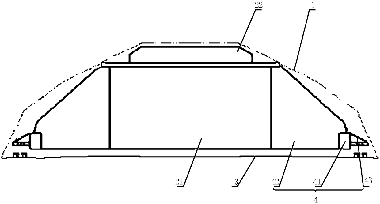
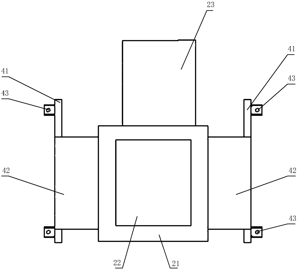
[0032] Please refer to figure 1 with figure 2 , figure 1 A schematic diagram of a partial structure of a rail transit vehicle provided by a specific embodiment of the present invention; figure 2 for figure 1 t...


PUM


Abstract

A rail transit vehicle including car body and traction transformer, the traction transformer is fixed on the top of the vehicle body and the outer contour of the traction transformer is located in theroof contour line protruding in a direction away from the bottom surface of the vehicle body, Setting the traction transformer at the top of the car body and ensuring that the outer contour of the traction transformer is located in the contour line of the car roof is not only beneficial to avoiding the damage of pollution, blockage and scratch of the traction transformer to a certain extent, butalso prolongs the service life by reducing the failure rate and improves the working reliability of the rail transit vehicles. But also helps to reduce the height of the bottom surface of the car bodyfrom the ground, avoid adding a higher platform, and weaken the influence of the platform height, so as to improve its adaptability. Therefore, the rail transit vehicle provided by the invention is conducive to improving its working reliability and adaptability.

Description

technical field [0001] The invention relates to the technical field of rail transit, in particular to a rail transit vehicle. Background technique [0002] The traction transformer used for rail transit vehicles is a power transformer with a special voltage level. It is usually used to convert the 25KV high-voltage voltage obtained from the catenary into a suitable voltage for the traction motor and other motors and electrical appliances. It needs to meet the traction requirements during work. To meet the requirements of drastic load changes, it is necessary to suppress harmonic current and limit short-circuit current to ensure the safe, stable and reliable operation of rail transit vehicles. Therefore, traction transformers are the core and key components of rail transit vehicles. [0003] Existing traction transformers generally include iron cores, windings, oil tanks, oil storage tanks, cooling systems, bushings, transformer oil, etc., wherein the iron core and windings g...

Claims


Application Information

Patent Timeline
Patent Type & Authority Applications(China)
IPC IPC(8): H01F27/06H01F27/14B61C3/00
CPCB61C3/00H01F27/06H01F27/14B61D17/00
Inventor 胡贵钟珩朱莉莉何泽海吴勇阳清泉刘婷
Owner CSR ZHUZHOU ELECTRIC CO LTD
Why Eureka
Try Eureka