
A power connection assembly used for assembling internal components of communication electronic instruments

A technology for electronic instruments and internal components, applied in the field of electrical components for electronic components, can solve the problems of wire falling off, trouble, low efficiency, etc., and achieve the effect of fast power-on

Inactive Publication Date: 2020-07-24
夏彬 +1
View PDF3 Cites 0 Cited by
  • Summary
  • Abstract
  • Description
  • Claims
  • Application Information

AI Technical Summary

Problems solved by technology

[0004] The purpose of the present invention is to provide a power connection assembly for the assembly of internal components of communication electronic instruments, which can solve the problem that traditional communication electronic instruments generally use manual power connection during the assembly process. Manual power connection is not only low in efficiency and speed Slow, and the connected wires are easy to fall off from the components. At the same time, the electronic components after manual power-on are also extremely inconvenient when power-off is required. Manual disassembly is required, which is not only troublesome but also unable to meet the needs of fast power-off. question

Method used


Image

  • A power connection assembly used for assembling internal components of communication electronic instruments
  • A power connection assembly used for assembling internal components of communication electronic instruments
  • A power connection assembly used for assembling internal components of communication electronic instruments

Examples


Embodiment Construction

[0027] The technical solutions of the present invention will be clearly and completely described below in conjunction with the embodiments. Apparently, the described embodiments are only some of the embodiments of the present invention, not all of them. Based on the embodiments of the present invention, all other embodiments obtained by persons of ordinary skill in the art without creative efforts fall within the protection scope of the present invention.

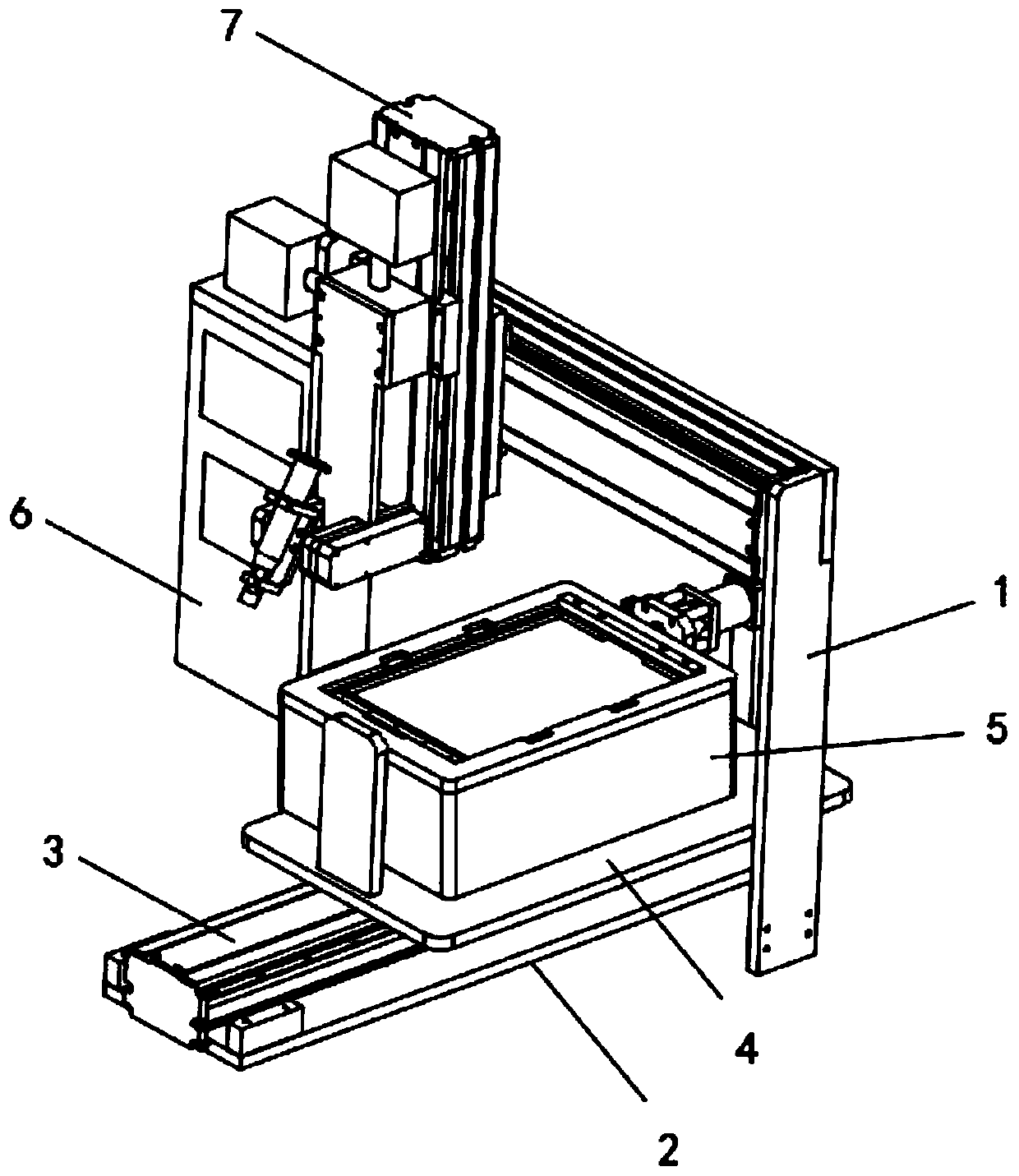
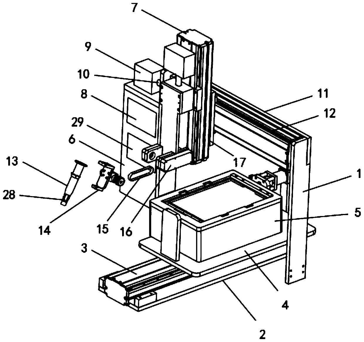
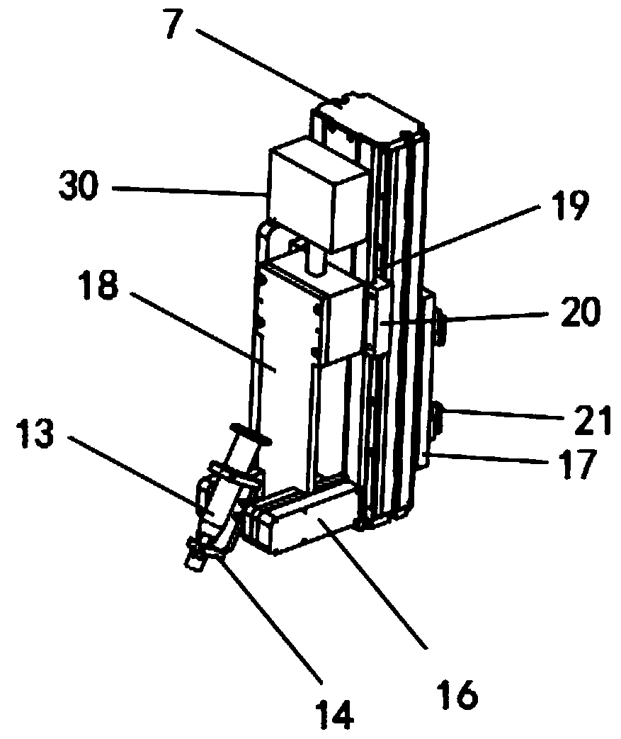
[0028] see Figure 1-5 As shown, a power connection assembly for the assembly of internal components of communication electronic instruments includes a bracket 1 and a side frame 6 located on one side wall of the bracket 1. A cross bar 11 is arranged on the top of the bracket 1, and a Y Axis 12, Z-axis 7 is installed on the side wall of Y-axis 12, and Z-axis 7 can move and adjust its position along the direction of Y-axis 12, so as to facilitate the positional docking between hollow wire tube 13 and terminal 27, and the sid...


PUM


Abstract

An electrical connector assembly for assembling internal components of a communication electronic instrument, the invention can solve the problem that the traditional communication electronic instruments usually adopt the manual power connection method in the assembly process, Manual power connection is not only inefficient and slow, but also the wires are easy to fall off from the components. Atthe same time, the electronic components after manual power connection are extremely inconvenient when the power is needed to be cut off, and manual power disassembly is needed, which is not only troublesome but also unable to meet the demand of fast power cut. Includes a bracket and a side frame located on a side wall at one end thereof, A cross bar is arranged on the top of the bracket, A Y-axisis arrange on that sidewall of the cross bar, a Z-axis is arranged on the sidewall of the Y-axis, a movable plate is arrange on the sidewall of the Z-axis, a hollow wiring pipe is arranged on the bottom end of the movable plate, a base is arranged on the bottom of the support, an X-axis is arrange on the base, a slide plate is arranged on the top of the X-axis, and an element box is arranged on the top of the slide plate.

Description

technical field [0001] The invention relates to an electrical connection assembly for electronic components, in particular to an electrical connection assembly used for assembling internal components of communication electronic instruments. Background technique [0002] When the internal components of communication electronic instruments are assembled, it is necessary to connect the electronic components to the power supply and connect the electronic components to the power supply so that they can operate normally. [0003] The current communication electronic equipment generally adopts the method of manual power connection during the assembly process. Manual power connection is not only inefficient and slow, but also the connected wires are easy to fall off from the components. At the same time, the electronic components after manual power connection are in need It is also extremely inconvenient when the power is cut off, and it needs to be disassembled manually, which is n...

Claims


Application Information

Patent Timeline
Patent Type & Authority Patents(China)
IPC IPC(8): H01R43/26
CPCH01R43/26
Inventor 夏彬狄祥
Owner 夏彬
Learn More