
Dust-proof heat dissipation switch cabinet

A heat-dissipating switch and dust-proof technology, applied in the substation/switch layout details, substation/switchgear cooling/ventilation, electrical components, etc., can solve the problems of safety hazards, circuit safety hazards, slow heat dissipation of switch cabinets, etc.

Inactive Publication Date: 2018-12-18
镇江宝源电仪设备有限公司
View PDF2 Cites 0 Cited by
  • Summary
  • Abstract
  • Description
  • Claims
  • Application Information

AI Technical Summary

Problems solved by technology

The heat dissipation of the switchgear is slow, and when the circuit is running, the heat is concentrated and cannot be dissipated in time, causing safety hazards
At the same time, when the switchgear is not sealed and the heat is dissipated quickly, the entry of dust may cause potential safety hazards in the circuit

Method used


Image

  • Dust-proof heat dissipation switch cabinet

Examples


Embodiment 1

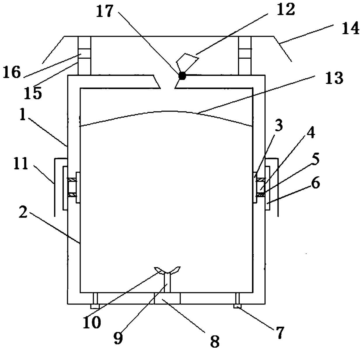
[0017] like figure 1 As shown, a dust-proof and heat-dissipating switch cabinet of the present invention includes a cabinet body, and the cabinet body includes an outer body 1 and an inner cavity body 2. There is a cavity structure between the outer body body 1 and the inner cavity body 2, and the outer body body 1 and the inner cavity body The cavity 2 is connected by bolts 7; the bottom of the inner cavity 2 is provided with a fan blade 10, the fan blade 10 is connected with the power supply 8 through the first rotating shaft 9, the power supply 8 is arranged in the cavity structure, and the inner cavity 2 is provided with a metal Silk screen 13; the outer surface of the inner cavity body 2 is provided with a heat dissipation plate, the outer surface of the outer shell 1 is provided with a second heat dissipation plate 6, and a semiconductor cooling plate 4 is arranged between the first heat dissipation plate 3 and the second heat dissipation plate 6, and the first The heat ...

Embodiment 2

[0024] like figure 1 As shown, a dust-proof and heat-dissipating switch cabinet of the present invention includes a cabinet body, and the cabinet body includes an outer body 1 and an inner cavity body 2. There is a cavity structure between the outer body body 1 and the inner cavity body 2, and the outer body body 1 and the inner cavity body The cavity 2 is connected by bolts 7; the bottom of the inner cavity 2 is provided with a fan blade 10, the fan blade 10 is connected with the power supply 8 through the first rotating shaft 9, the power supply 8 is arranged in the cavity structure, and the inner cavity 2 is provided with a metal Silk screen 13; the outer surface of the inner cavity body 2 is provided with a heat dissipation plate, the outer surface of the outer shell 1 is provided with a second heat dissipation plate 6, and a semiconductor cooling plate 4 is arranged between the first heat dissipation plate 3 and the second heat dissipation plate 6, and the first The heat ...


PUM


Abstract

The invention discloses a dust-proof and heat-dissipating switch cabinet, comprising a cabinet body, wherein the cabinet body comprises an outer shell body and an inner cavity body; the outer shell body and the inner cavity body are provided with a hollow cavity structure; the outer shell body and the inner cavity body are connected with each other through bolts; A fan blade is arranged at the bottom of the inner cavity, the fan blade is connected with a power supply through a first rotating shaft, the power supply is arranged in the cavity structure, and a metal wire mesh is arranged in the inner cavity; A screw cap is arranged at the top of the cabinet body, and the screw cap is connected with the top of the cabinet body through a second rotating shaft; A dust cap is arranged on the topof the shell body, and is connected with the top of the shell body through bolts. At that same time, the dust-proof cover and the metal wire mesh are arranged so as to prevent dust from enter into theinterior of the cabinet when the rotary cover is opened and communicated with the outside, thereby causing safety hidden trouble and cleaning problems. The invention has fan blade and rotary cover for realizing rapid heat dissipation. The heat dissipation plate and the semiconductor refrigeration fin provided by the invention can dissipate heat of the internal cabinet body without fast heat dissipation.

Description

technical field [0001] The invention relates to a dust-proof and heat-dissipating switchgear, which belongs to the field of electrical machinery equipment. Background technique [0002] A switchgear is an electrical device used to control the on and off of various devices. The heat dissipation of the switchgear is relatively slow. When the circuit is running, the heat is concentrated and cannot be dissipated in time, causing potential safety hazards. At the same time, when the switchgear is not sealed and the heat is dissipated rapidly, the entry of dust may cause potential safety hazards in the circuit. Contents of the invention [0003] The technical problem to be solved by the present invention is to overcome the defects of the prior art and provide a dust-proof and heat-dissipating switchgear, which can effectively prevent dust and dissipate heat, and avoid potential safety hazards caused by overheating of the cabinet and dust entry. [0004] In order to solve the ab...

Claims


Application Information

Patent Timeline
Patent Type & Authority Applications(China)
IPC IPC(8): H02B1/30H02B1/56H02B1/28
CPCH02B1/30H02B1/28H02B1/565
Inventor 刘良宝
Owner 镇江宝源电仪设备有限公司
Learn More