Inertial linear piezoelectric motor

A piezoelectric motor and linear technology, applied to electrical components, piezoelectric effect/electrostrictive or magnetostrictive motors, generators/motors, etc., can solve the problems of low motor efficiency and high efficiency, and achieve improved efficiency, The effect of low noise and low matching circuit requirements

Active Publication Date: 2018-12-18
HEFEI UNIV OF TECH
View PDF7 Cites 9 Cited by
  • Summary
  • Abstract
  • Description
  • Claims
  • Application Information

AI Technical Summary

Problems solved by technology

The inertial impact piezoelectric motor uses the principle of inertial impact to drive the motor movement, which can be divided into two types: asymmetric signal type and asymmetric structure type; the asymmetric signal inertia motor is driven by a sawtooth wave signal, and the stator obtains asymmetric acceleration during the round-trip process, thus The mover is driven to move under the action of inertia, but the asymmetric signal inertia motor cannot work in a resonance state, and the motor efficiency is low; see Figure 8 , the asymmetric structure inertia motor drives the mover through the inertia generated by the structural difference of the two processes of stator movement and return. The asymmetric structure inertia motor works in a resonant state and has high efficiency; the existing asymmetric structure inertia motor can only move to one Direction movement and reverse movement need to manually reverse the direction of the motor, so the problem to be solved is how to make the motor work in a resonance state, and at the same time realize the conversion of the forward and reverse movement of the motor on the premise of only changing the input signal

Method used


Image

  • Inertial linear piezoelectric motor
  • Inertial linear piezoelectric motor
  • Inertial linear piezoelectric motor

Examples


Embodiment

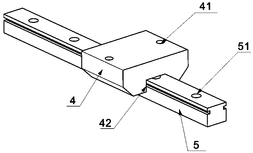
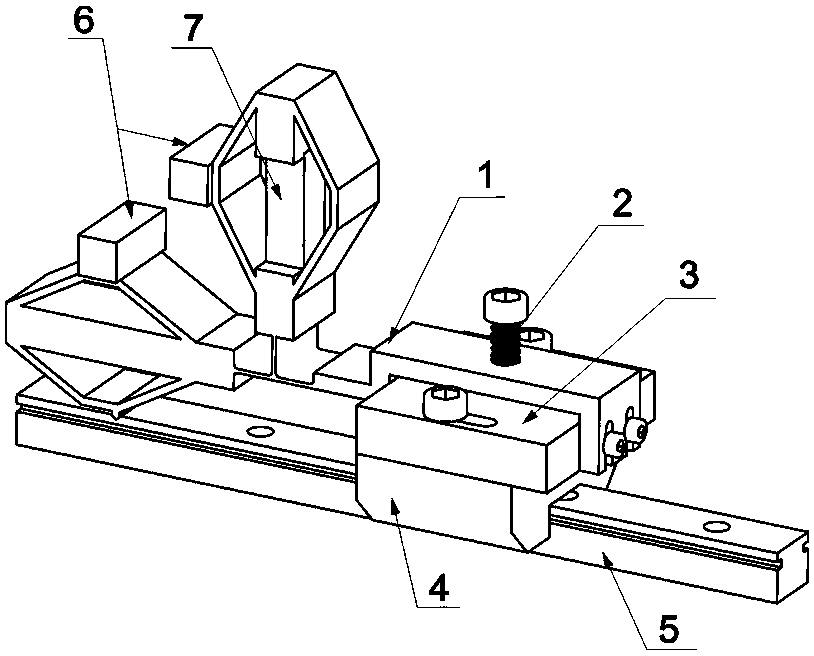
[0032] see figure 1 , an inertial linear piezoelectric motor includes a bottom plate 1, a slider 4, a slide rail 5, two mass blocks 6 and a piezoelectric stack 7. The piezoelectric stack 7 is formed by stacking several piezoelectric sheets, and the material of the piezoelectric sheets is Piezoelectric Ceramics.

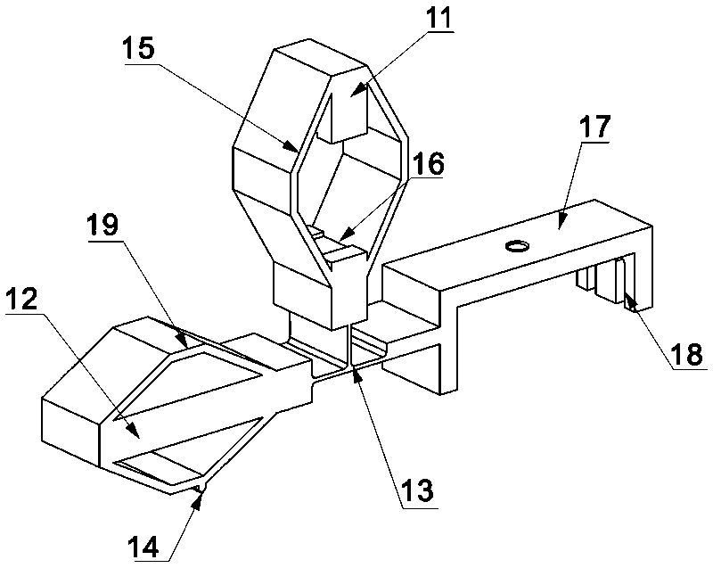
[0033] see figure 1 and figure 2 , the bottom plate 1 is a strip-shaped plate, one end is connected to the slider 4, and the other end is respectively connected to the vertical structural member 11 and the horizontal structural member 12 through a flexible hinge 13, and the flexible hinge 13 is a T-shaped thin plate structure. The vertical structural member 11 and the horizontal structural member 12 are hollow diamond-shaped structural members with the same structure. A mass block 6 is installed on the outer middle part of the vertical structural member 11 adjacent to the horizontal structural member 12, and another mass block 6 is installed on the outer middle ...


PUM


Abstract

The invention relates to an inertial linear piezoelectric motor. Comprises a bottom plate, a slider, a sliding rail, two mass blocks and a piezoelectric stack; The bottom plate is an elongated plate,one end of which is connected with a slider, and the other end of which is connected with a vertical structure part and a horizontal structure part through a flexure hinge. The vertical structure andthe horizontal structure are hollow rhombus structure with the same structure. The piezoelectric stack is arranged in the hollow rhombus structure of the vertical structure part; the piezoelectric stack is arranged in the hollow rhombus structure of the vertical structure part; The slider is fitted on the slide rail to realize linear sliding along the slide rail. When a harmonic signal of a firstorder frequency is inputted to the piezoelectric stack to produce a first order resonant mode, the whole inertial linear piezoelectric motor moves to the right, and when a harmonic signal of a secondorder frequency is inputted to the piezoelectric stack to produce a second order vibration mode, the whole inertial linear piezoelectric motor moves to the left; As that frequency of the harmonic signal apply to the piezoelectric stack is changed, different vibration mode of the motor can be generated and the movement direction of the motor can be changed.

Description

technical field [0001] The invention belongs to the technical field of precision driving and positioning, and in particular relates to an inertia linear piezoelectric motor. Background technique [0002] Piezoelectric motors are gradually increasing in demand in today's scientific and industrial fields. They have the characteristics of simple principle, compact structure, high precision, and fast response. The inertial impact piezoelectric motor uses the principle of inertial impact to drive the motor movement, which can be divided into two types: asymmetric signal type and asymmetric structure type; the asymmetric signal inertia motor is driven by a sawtooth wave signal, and the stator obtains asymmetric acceleration during the round-trip process, thus The mover is driven to move under the action of inertia, but the asymmetric signal inertia motor cannot work in a resonance state, and the motor efficiency is low; see Figure 8 , the asymmetric structure inertia motor drives...

Claims


Application Information

Patent Timeline
Patent Type & Authority Applications(China)
IPC IPC(8): H02N2/04
CPCH02N2/021H02N2/04
Inventor 贺良国徐磊王勇潘巧生葛新方楚宇恒郝赛赵杰
Owner HEFEI UNIV OF TECH
Why Eureka
Try Eureka