
An address code identifying method for on-load driving of a plurality of parallel LED lamp bodies by a power line

A technology of LED lamp body and identification method, applied in the field of address code identification, can solve the problems of difficult replacement, inability to divide lamp strings, inability to know the actual address code of lamp beads, etc., and achieve the effect of simplifying the difficulty of operation

Active Publication Date: 2018-12-18
POWER MOS MICROELECTRONICS LTD +1
View PDF9 Cites 13 Cited by
  • Summary
  • Abstract
  • Description
  • Claims
  • Application Information

AI Technical Summary

Problems solved by technology

However, each lamp bead has an independent address code that must be followed by a specific main controller, and these address codes are stored in the memory unit of the main controller matching the light string combined with the address code, and cannot be combined with multiple address codes. The lamp string composed of lamp beads is divided, and the actual address code of the lamp beads cannot be known. If some lamp beads are abnormal or fail during use, it is difficult to replace them

Method used


Image

  • An address code identifying method for on-load driving of a plurality of parallel LED lamp bodies by a power line

Examples


specific Embodiment approach 1

[0027] Specific implementation mode 1: The address code identification method for the power line to drive a light string composed of multiple parallel replaceable screw-mounted LED bulbs

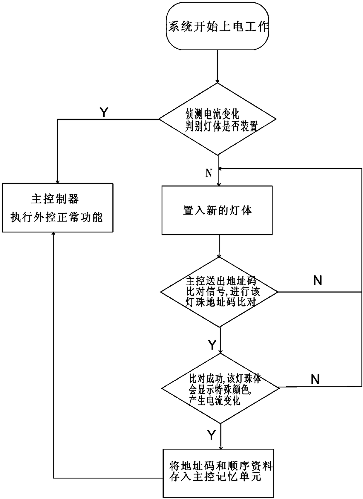
[0028] Connect the power cable including the female socket that has been connected to the main controller but not installed with the smart bulb to the predetermined DC power supply. After the system starts to power on, the following steps are included:

[0029]1) Detect current changes and judge whether the lamp body is installed or not. The basis for judging is that each smart light bulb has a fixed static current. If the overall power consumption is lower than the set value, it means that the light string is in an empty state and automatically adjusts to a new light bulb. put into mode;

[0030] 2) If the lamp body is installed, the main controller performs the normal function of external control; if the lamp body is not installed, one by one and only one new lamp body can be inserted at t...

specific Embodiment approach 2

[0034] Specific implementation mode 2: Address code recognition method for intelligent light-emitting building block toys that drive multiple parallel replaceable screw-mounted LED bulbs with power cords

[0035] Intelligent light-emitting building block toys refer to toys that can use the main controller to transmit accurate data to each building block light-emitting unit, so that each building block light-emitting unit can perform different color changes according to the signal of the main controller. Intelligent light-emitting building blocks can be randomly stacked without numbering each building block, that is, the order of assembly can be linked with the address code, so that the main controller can accurately control each building block. The address code identification method is basically the same as that of the specific embodiment. There are no long-distance power lines between the building blocks, and the transmission signal paths are not arranged in a one-line order, ...


PUM


Abstract

An address code identifying method for on-load driving of a plurality of parallel LED lamp bodies by a power line comprises the following steps: 1) detecting a current change; 2) for uninstalled lampbodies, placing lamp bodies one by one, and only one new lamp body being allowed to be placed at the same time; 3) for installed lamp bodies, storing the address code and the sequence data in the memory unit of a main controller, and for uninstalled lamp bodies, the main controller sending out an address code comparison signal; 4) if the address code comparison of the new lamp body is not successful, returning to Step 2) and placing a new lamp body again; and 5) sequentially repeating Steps 3) to 4) till the new lamp body display a special color and generates current change, and storing the address code and the sequence data in the memory unit of the main controller. The method loweres the operation difficulty, does not need professional operation, does not need to use address detection tools including an external photosensitive device photodiode and a camera tube, assembly can be performed at will according to a sequence and a defective product can be replaced, and the installation ofa plurality of parallel LED lamp bodies by a customer becomes feasible.

Description

technical field [0001] The invention relates to an LED lamp body, in particular to an address code identification method for driving a plurality of parallel LED lamp bodies with a signal carried by a power line. Background technique [0002] Urban lighting and holiday decoration lights have been upgraded from the embellishment effect of only flashing lights to intelligent applications such as using external signals to control demonstration patterns to present text information. Using the power line to integrate data transmission is one of the external single-point controllable technologies, which requires the main controller to confirm the specific location of each lamp body and the corresponding address code, and accurately transmit the control signal to each independent lamp body. In order to achieve the state of being recognized by the main control, each lamp body must be implanted with a smart chip or circuit board that can distinguish independent addresses to each lamp b...

Claims


Application Information

Patent Timeline
IPC IPC(8): H05B33/08H05B44/00
CPCH05B45/30H05B45/52H05B47/19H05B45/20
Inventor 赖政章
Owner POWER MOS MICROELECTRONICS LTD
Learn More