Indoor aquaculture surrounding cell experiment device
An experimental device and aquaculture technology, applied in fish farming, application, animal husbandry, etc., can solve problems that affect the final results of marginal experimental organisms, and achieve the effect of promoting environmental consistency, uniform water supply, and high utilization rate
- Summary
- Abstract
- Description
- Claims
- Application Information
AI Technical Summary
Problems solved by technology
Method used
Image

Examples
Embodiment 1
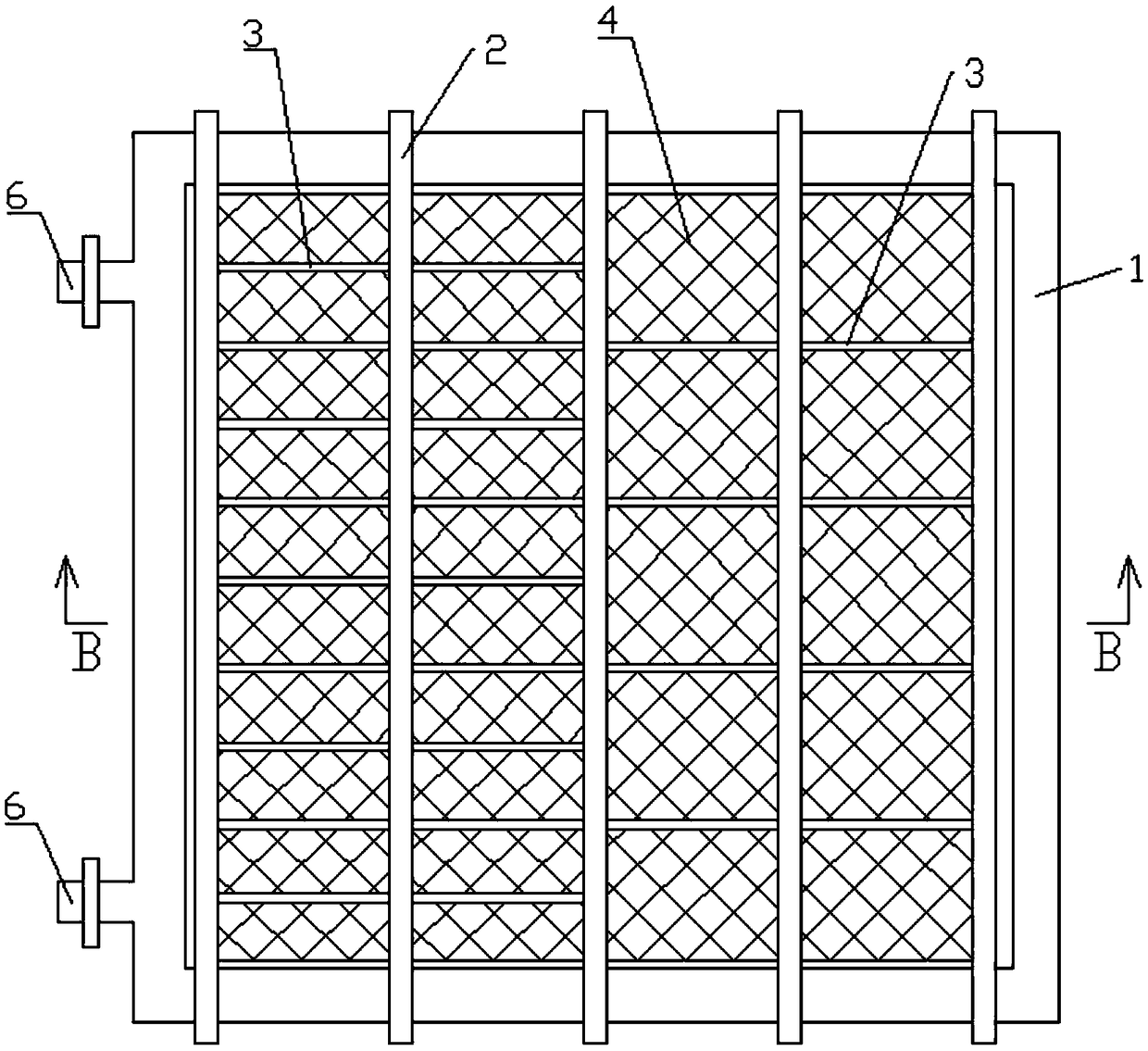
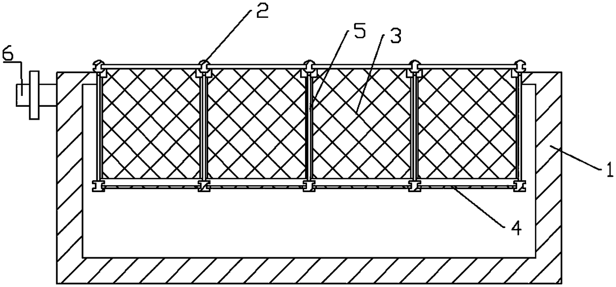
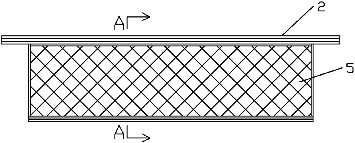
[0033] The purpose of the present invention can be achieved through the following technical solutions: an indoor aquaculture enclosure experiment device, comprising a water tank 1, several support rods 2, several coaming plates 3 and several bottom plates 4, and the support rods 2 are parallel and evenly distributed On the notch of the water tank 1, the lower end of the support rod 2 is fixedly provided with a side plate 5 parallel to the shaft, and the side plate 5 extends into the water tank 1, and the two sides of the support rod 2 A slot one 21 parallel to the shaft is provided, a slot two 51 parallel to the board surface is provided on both sides of the lower side of the side plate 5; 31, the lower end of the coaming plate 3 is provided with two inserting rods 32, and the two sides of the bottom plate 4 are provided with inserting rods three 41; In slot one 21, at the same time, the two ends of said insertion rod two 32 are slidably inserted into two opposite slots two 51...
Embodiment 2
[0046] This embodiment is implemented using the device structure described in Embodiment 1, the difference is that
[0047] The inside of the support rod and the insertion rod is hollow, the inside of the support rod is provided with a water guide pipe 22, and the water guide pipe 22 is connected with the water inlet, and a number of water guide pipes are arranged in the slot of the support rod. 22 is connected to the water supply interface 23, and the water supply interface 23 is provided with a valve 24; a plurality of nozzles 34 are arranged on the top of the first insertion rod, and a water supply joint 33 is provided at both ends of the first insertion rod, and the first insertion rod can pass through the water supply joint 33 It is sealingly connected with the water supply interface 23 of the water conduit 22 . In the support rod, the valve 24 is a solenoid valve. The nozzle 34 is a mist water supply nozzle.
[0048] The upper and lower sides of the water supply interf...
Embodiment 3
[0052] This embodiment is implemented using the device structure described in Embodiment 2, the difference is that
[0053] The water supply interface and the water supply joint are connected through a telescopic hose, and the telescopic hose is arranged in the support rod, and the two ends of the telescopic hose are respectively connected to the water supply interface and the water supply joint through threads. Sealed connection. The telescopic hose can not only ensure the normal water supply of the coaming, but also enable the coaming to be adjusted freely along the position inside the support rod, which further facilitates the adjustment and improves the experimental efficiency.
PUM
 Abstract
Description
Claims
Application Information
 - R&D
- Intellectual Property
- Life Sciences
- Materials
- Tech Scout
- Unparalleled Data Quality
- Higher Quality Content
- 60% Fewer Hallucinations
Browse by: Latest US Patents, China's latest patents, Technical Efficacy Thesaurus, Application Domain, Technology Topic, Popular Technical Reports.
© 2025 PatSnap. All rights reserved.Legal|Privacy policy|Modern Slavery Act Transparency Statement|Sitemap|About US| Contact US: help@patsnap.com