
Wave Power Equipment

A wave power generation and equipment technology, applied in ocean energy power generation, mechanical equipment, hydropower, etc., can solve problems such as equipment loss, increased production, and energy loss, and reduce the cost of pipeline maintenance, reduce the length of connecting pipelines, The effect of energy loss reduction

Inactive Publication Date: 2016-03-30
鲍里斯·弗拉基米罗维奇·希尔维斯特罗夫 +1
View PDF3 Cites 0 Cited by
  • Summary
  • Abstract
  • Description
  • Claims
  • Application Information

AI Technical Summary

Problems solved by technology

[0004] The deficiencies of the designs described above result in a significant loss of energy in use with today's equipment, which is due to the fluid resistance that occurs when water enters the tank through the pipes from the open water surface
During use, the surface inside the pipeline will be quickly polluted by pumping in seawater, making the inner diameter of the pipeline smaller and usually causing the equipment to lose some efficiency, because the water capacity becomes smaller and the cost of additional replacement pipelines is increased, thereby increasing The cost of using the above equipment
[0005] Another disadvantage is the instability of the floating pump support system
When the waves are high, there is a direct upward force that affects the flotation device, which can cause a dragging movement of the anchor, which can capsize the entire system
[0006] Another disadvantage is the known inefficiency of the floating system, which reduces the efficiency of the use of waves
Many floating systems connected to it have to be installed over a large area to increase production efficiency, which in turn increases manufacturing, installation and operating costs

Method used


Image

  • Wave Power Equipment
  • Wave Power Equipment
  • Wave Power Equipment

Examples


Embodiment Construction

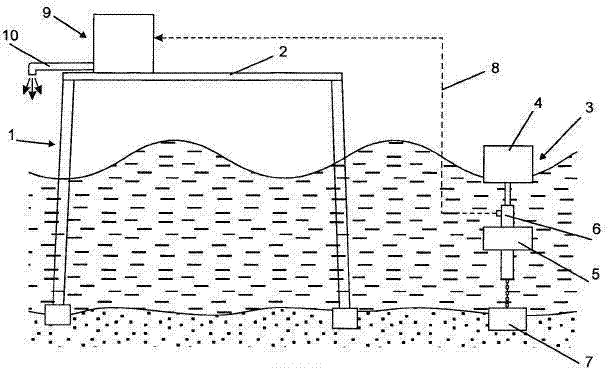
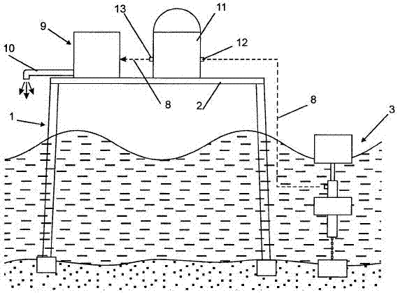
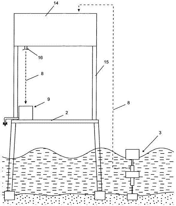
[0038] Position 1 in the figure is an offshore unit that is firmly installed in open water. The platform 2 floats on the sea surface and is installed on the offshore device 1 . Figure 1-4 The position 3 shown is a floating water pump comprising two floating devices 4 and 5 and a water pump 6 . Floating device 5 is positioned under water, directly connects water pump machine 6, and makes it be in the position under water surface all the time by anchor 7 and chain.

[0039] The floating device 4 is located on the water surface and is connected to the pole of the water pump machine 6 . As the floating device 4 moves with the sea waves, it acts on the rods of the pumps so that sea water is pumped into the pipe 8 to transfer the sea water from the floating pumps 3 to the turbines 9 on the platform 2 carrying the generators. A drain hole 10 is arranged on the water turbine 9 to allow the sewage to incline to open waters.

[0040] exist figure 2 , in the water supply system fro...


PUM


Abstract

Invention relates to devises for conversion of the energy of waves into electric energy and solves a problem of reliability improvement and operating efficiency of the wave power plant, reduction of hydraulic losses when water is pumping over pipeline as well as reduction of expenses for manufacturing, installation and operation. Solution of the problem stated is obtained hereby that the known wave power plant comprises at least one floating-type water pump, hydraulic turbine with electric generator, pipeline connecting water pump with hydraulic turbine additionally comprises offshore unit with platform placed above sea surface when hydraulic turbine with electric generator are installed at the platform. The suggested plant can additionally comprise damper or accumulative tank placed at the platform. The suggested plant can be equipped with crane as well. In this case the floating-type water pump in suggested wave power plant can be installed directly at the platform at its low part and provide with water supply both while float goes only down and when float moves in both directions - up and down. Moreover the floating-type water pump installed below can be fixed at removable part of the platform and be lifted above the platform by means of crane during installation works or maintenance. Implementation of the given invention can be put into effect at both specially constructed for this plant new offshore units and at the already existed offshore units.

Description

technical field [0001] The invention relates to the field of renewable energy, in particular to a device capable of converting hydraulic energy into electric energy. Background technique [0002] The currently used wave power generation equipment includes at least one suspended water pump, a generating turbine and a pipeline connecting the water pump and the turbine (refer to patent RFNO: 2316670). In addition, the device also includes a vertical bearing installed in the lower part of the open water, with a swinging rod, and on its upper part, a floating device is installed. The floating device is installed at the end of one end of the rod, and the other end of the rod is physically connected to the water pump. The water turbine carrying the generator is located on the shore, and the pipeline that supplies water between the water pump and the turbine through an intermediary tank is also located on the mountain, and the waste water is transported back to the open water throug...

Claims


Application Information

Patent Timeline
IPC IPC(8): F03B13/12F03B13/18
CPCF03B13/06F03B13/187F03B13/1875F04B9/10F05B2260/406Y02E10/20Y02E10/30Y02E60/16Y02P90/50
Inventor 鲍里斯·弗拉基米罗维奇·希尔维斯特罗夫
Owner 鲍里斯·弗拉基米罗维奇·希尔维斯特罗夫
Learn More