Electrical automatic spraying device

A technology of electrical automation and spraying devices, applied in the direction of combined devices, transportation and packaging, chemical instruments and methods, etc., can solve problems such as simple structure, physical hazards, and people's illnesses, and achieve reasonable design, pollution avoidance, and strong exhaust gas The effect of processing power

Inactive Publication Date: 2018-12-21
INNER MONGOLIA UNIV FOR THE NATITIES
View PDF7 Cites 6 Cited by
  • Summary
  • Abstract
  • Description
  • Claims
  • Application Information

AI Technical Summary

Problems solved by technology

[0002] With the development of society, the problem of environmental pollution has become more and more serious, and with the progress of industrialization, various exhaust gases have been discharged, followed by frequent occurrences of smog and acid rain, the earth we live on The air quality is getting worse and worse. Such an environment is very unfavorable to our human survival and will cause serious harm to our bodies. These harmful gases enter our respiratory system as we breathe, causing damage to various organs in our body , which causes people to get sick, and also brings a heavy burden to the society; therefore, we need to treat the waste gas at the source of the waste gas. The structure of the automatic spraying device is simple, and the waste gas cannot be thoroughly sprayed, resulting in the discharge of harmful substances in the waste gas, resulting in incomplete treatment of the waste gas and still polluting the environment; therefore, we propose an electric automatic spraying device

Method used


Image

  • Electrical automatic spraying device
  • Electrical automatic spraying device
  • Electrical automatic spraying device

Examples


Embodiment Construction

[0017] The following will clearly and completely describe the technical solutions in the embodiments of the present invention with reference to the accompanying drawings in the embodiments of the present invention. Obviously, the described embodiments are only some, not all, embodiments of the present invention. Based on the embodiments of the present invention, all other embodiments obtained by persons of ordinary skill in the art without making creative efforts belong to the protection scope of the present invention.

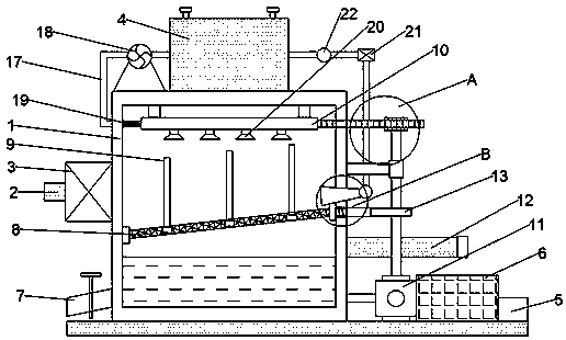
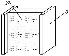
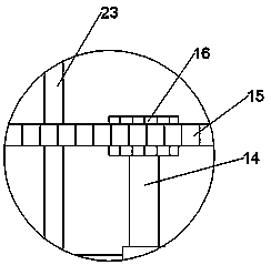
[0018] see Figure 1~4 , in an embodiment of the present invention, an electric automatic spraying device includes a spray chamber 1, a water storage tank 4, a filter screen 8, a drain pipe 10, a nozzle 20 and a spoiler net 27, and the upper surface of the spray chamber 1 The water storage tank 4 is fixedly welded, the air inlet pipe 2 is arranged in the middle position of the left side wall of the spray chamber 1, and the fan 3 is arranged between the air inl...


PUM


Abstract

The invention discloses an electrical automatic spraying device. The electrical automatic spraying device comprises a spraying chamber, a water storage tank, a filter screen, a draining pipe and spraying heads, wherein the water storage tank is fixedly welded on the upper surface of the spraying chamber; an air inlet pipe is arranged at the middle position of the left side wall of the spraying chamber; a fan is arranged between the air inlet pipe and the water storage tank; the air inlet pipe is communicated with the fan; the fan is communicated with the spraying chamber; the draining pipe ishorizontally arranged at the top of the spraying chamber; the plurality of spraying heads are horizontally and uniformly distributed below the draining pipe and are communicated with the draining pipe. The electrical automatic spraying device is characterized in that the filter screen is obliquely arranged at the middle position inside the water storage tank and is horizontally and uniformly provided with a plurality of vertical guide rails. The electrical automatic spraying device disclosed by the invention achieves reasonable design and high waste gas treatment capacity, and can be used forsufficient spraying treatment on waste gases, so that harmful substances in the waste gases can be adsorbed, and the pollution of exhausted waste gases to the environment is avoided.

Description

technical field [0001] The invention relates to the technical field of spraying devices, in particular to an electric automatic spraying device. Background technique [0002] With the development of society, the problem of environmental pollution has become more and more serious, and with the progress of industrialization, various exhaust gases have been discharged, followed by frequent occurrences of smog and acid rain, the earth we live on The air quality is getting worse and worse. Such an environment is very unfavorable to our human survival and will cause serious harm to our bodies. These harmful gases enter our respiratory system as we breathe, causing damage to various organs in our body , which causes people to get sick, and also brings a heavy burden to the society; therefore, we need to treat the waste gas at the source of the waste gas. The structure of the automatic spraying device is simple, and the exhaust gas cannot be thoroughly sprayed, resulting in the dis...

Claims


Application Information

Patent Timeline
Patent Type & Authority Applications(China)
IPC IPC(8): B01D50/00B01D47/06B01D46/10B01D46/00B01D53/18
CPCB01D46/10B01D47/06B01D53/185B01D46/72B01D50/60
Inventor 乌兰
Owner INNER MONGOLIA UNIV FOR THE NATITIES
Why Eureka
Try Eureka