
Combined fluid distributor

A fluid distributor and combined technology, applied in chemical instruments and methods, feeding devices, chemical/physical processes, etc., can solve the problems of insufficient uniform flow, large shearing effect, unfavorable living conditions of microorganisms, etc., and achieve improved mixing. Uniformity, fluid uniformity

Pending Publication Date: 2018-12-21
CHINA ENFI ENGINEERING CORPORATION
View PDF0 Cites 1 Cited by
  • Summary
  • Abstract
  • Description
  • Claims
  • Application Information

AI Technical Summary

Problems solved by technology

[0003] In the prior art, the fluid flow rate at each outlet of the fluid distributor is not uniform enough. After the fluid enters the reactor, it cannot diffuse rapidly, which affects the mixing and reaction rate of the fluid in the reactor; the interlayer shear of the ejected fluid flow is too large , such as in an anaerobic reactor, when microorganisms are needed to promote the reaction, excessive flow layer shearing is often not conducive to maintaining suitable living conditions for microorganisms; moreover, the installation process of the existing fluid distributor is complicated, if somewhere The nozzle is blocked, and the subsequent disassembly and maintenance workload is heavy, which affects production efficiency

Method used


Image

  • Combined fluid distributor
  • Combined fluid distributor
  • Combined fluid distributor

Examples


Embodiment Construction

[0029] Example embodiments will now be described more fully with reference to the accompanying drawings. Example embodiments may, however, be embodied in many forms and should not be construed as limited to the embodiments set forth herein; rather, these embodiments are provided so that this disclosure will be thorough and complete, and will fully convey the concept of example embodiments to those skilled in the art. The same reference numerals in the drawings denote the same or similar structures, and thus their detailed descriptions will be omitted.

[0030] Although relative terms such as "top", "bottom", "upper", "lower", "inner" and "outer" are used in this specification to describe the relative relationship of one component of an icon to another component, these terms are used in this specification Instructions are for convenience only. If the device of the icon is turned over so that it is upside down, then the described "upper" component will become the "lower" compo...


PUM


Abstract

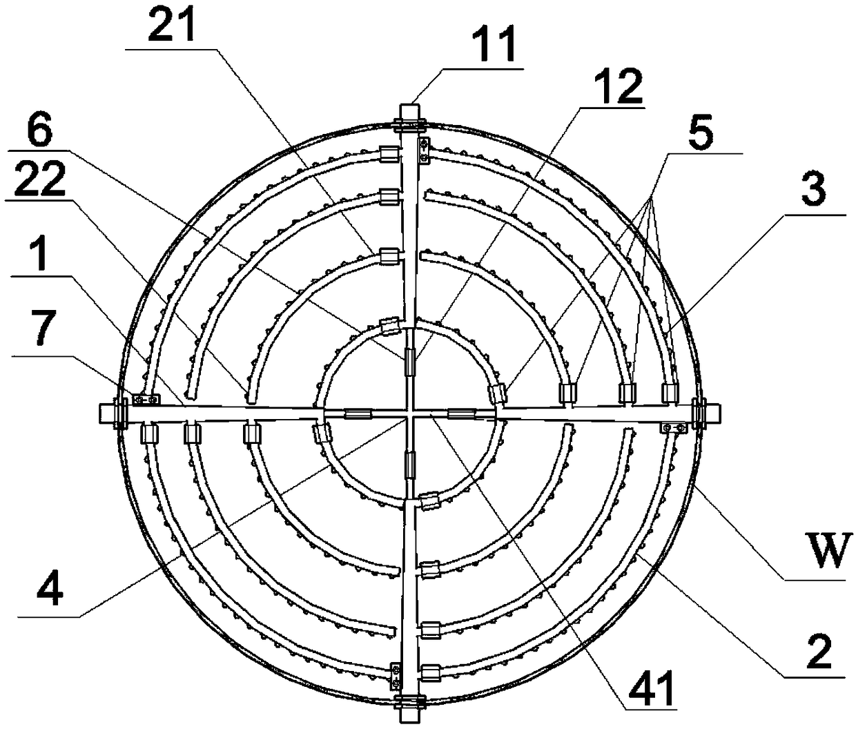
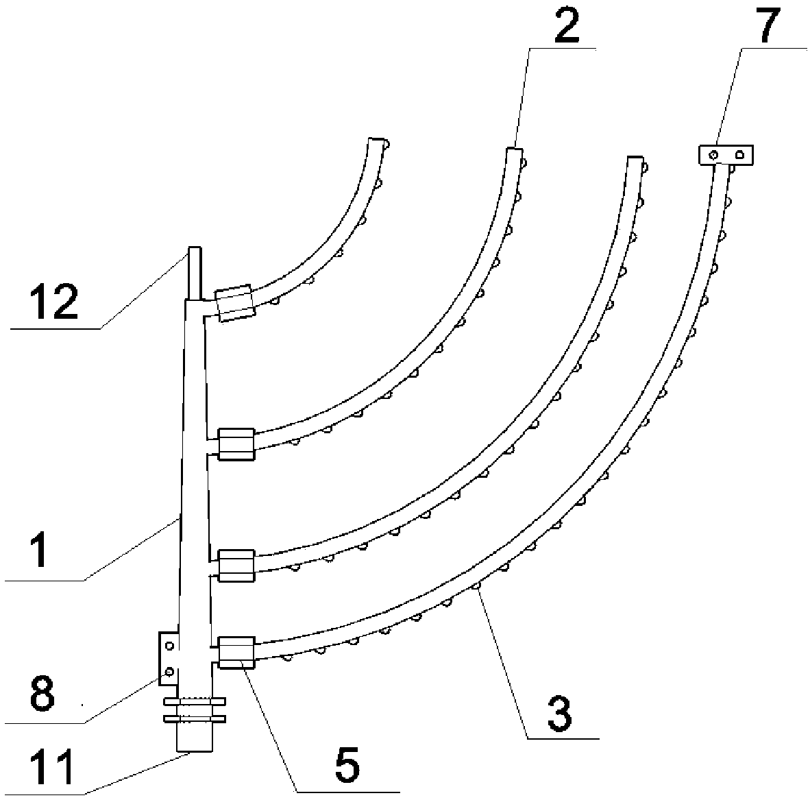
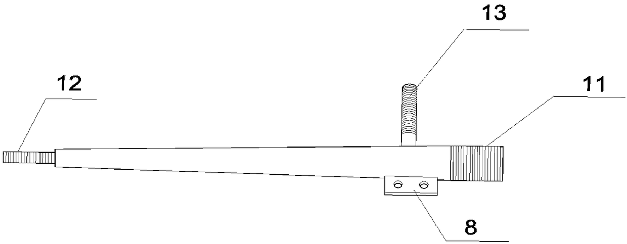
The invention provides a combined fluid distributor. The combined fluid distributor is arranged in a reactor and comprises a plurality of fluid main pipes, a central bracket, groups of arc branch pipes and a plurality of liquid outlet pipes, wherein each fluid main pipe is a straight pipe and has a first end and a second end, and the first end is detachably fixed on a tank wall of the reactor; a plurality of fluid main pipes are evenly distributed in the circumferential direction of a same circumferential plane, and the second end points to the center of the circle of the circumferential plane; the central bracket is detachably connected with the second end of each fluid main pipe; for the groups of arc branch pipes, each group of arc branch pipes is positioned between adjacent fluid mainpipes, and the arc branch pipes have communicating ends and closed ends, the communicating ends are communicated with the interior of the fluid main pipes, and the closed ends are completely closed; the groups of arc branch pipes form at least one circular ring structure in the circumferential plane; and the plurality of liquid outlet pipes are communicated with the interiors of the arc branch pipes. The combined fluid distributor provided by the invention sprays a more uniform fluid, thereby improving the mixing uniformity of the liquid in the reactor.

Description

technical field [0001] The invention relates to the technical fields of petroleum, chemical industry and environmental protection equipment, in particular to a combined fluid distributor. Background technique [0002] The function of the fluid distributor is to evenly distribute the fluid entering the reactor. It is widely used in chemical industry, environmental protection, medicine, food and other industrial fields. It is generally installed in fluidized beds, anaerobic reactors and tower reactors. In these devices, the uniformity of fluid distribution in these reactors is improved by spraying or spraying liquid or gas into these devices, so as to ensure the effect of reaction and separation. [0003] In the prior art, the fluid flow rate at each outlet of the fluid distributor is not uniform enough. After the fluid enters the reactor, it cannot diffuse rapidly, which affects the mixing and reaction rate of the fluid in the reactor; the interlayer shear of the ejected flui...

Claims


Application Information

Patent Timeline
IPC IPC(8): B01J4/00
CPCB01J4/002B01J2204/002
Inventor 孙铭阳姚心杨培培罗慧君李文赵永志田丽森
Owner CHINA ENFI ENGINEERING CORPORATION
Learn More