
Massive mineral reaction device

A technology of reaction equipment and minerals, applied in the direction of chemical/physical process, chemical/physical/physical chemical process, dissolution, etc., can solve the problems of long action time, slow reaction, damage to ore blocks, etc., to achieve reduced action time and convenient positioning , to avoid the effect of damage

Pending Publication Date: 2018-12-21
PANGANG GRP MINING
View PDF0 Cites 0 Cited by
  • Summary
  • Abstract
  • Description
  • Claims
  • Application Information

AI Technical Summary

Problems solved by technology

On the one hand, due to the small surface area of ​​the ore (compared to the particles under the same quality conditions), the reaction is slow; on the other hand, the ore is placed in a beaker and cannot be stirred by magnetic force. If magnetic stirring is used, the magnetic rotor will collide. For bad minerals, if a stirrer is used to stir above the ore block, since the ore block is not fixed, the water flow will drive the ore block to move, hit the container wall, and damage the ore block
Therefore the effect of ore nugget and medicament can only react in static liquid at present, so the action ability of ore nugget and medicament is weak, and the action time is more than 20 times longer than the flotation action time, and secondly also can not truly reflect flotation operation (medicine and medicament Mineral collision), which not only reduces the test efficiency and increases the test cost, but also it is difficult to simulate the real flotation operation during the test process, which reduces the credibility of the mechanism research
But so far, there is no rapid response equipment for massive minerals and medicines on the market.

Method used

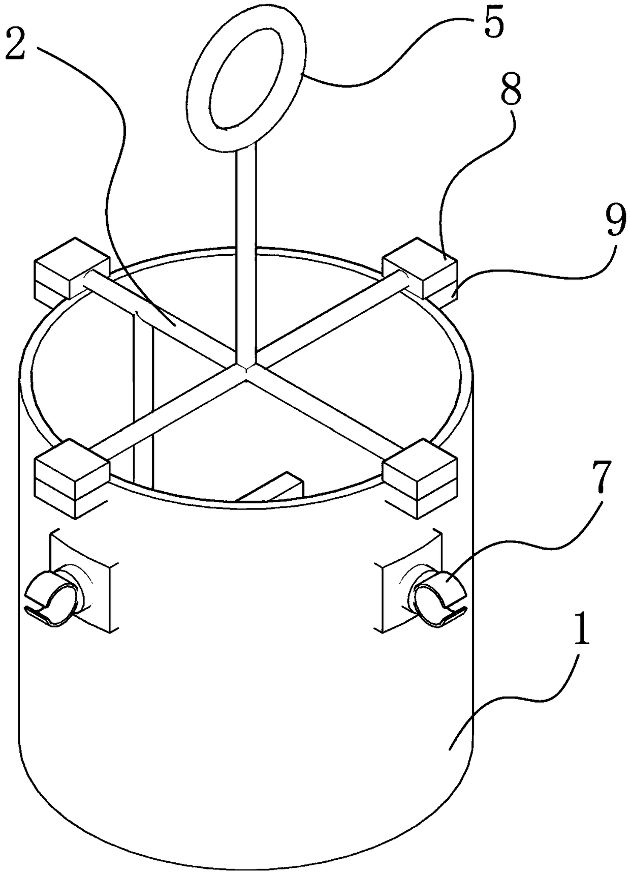

Image

  • Massive mineral reaction device
  • Massive mineral reaction device
  • Massive mineral reaction device

Examples


Embodiment Construction

[0023] The following will clearly and completely describe the technical solutions in the embodiments of the present invention with reference to the accompanying drawings in the embodiments of the present invention. Obviously, the described embodiments are only some, not all, embodiments of the present invention. Based on the embodiments of the present invention, all other embodiments obtained by persons of ordinary skill in the art without making creative efforts belong to the protection scope of the present invention.

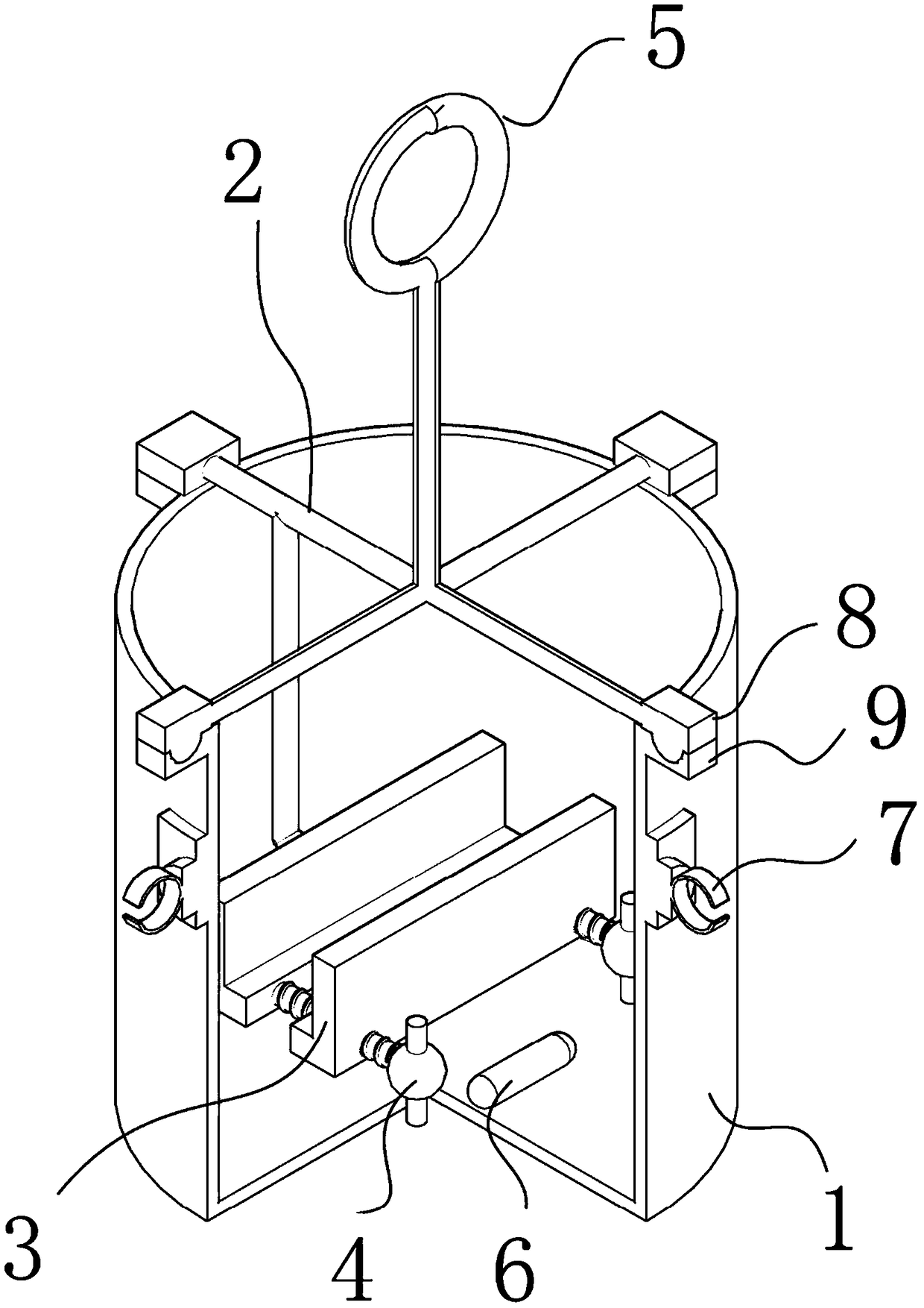
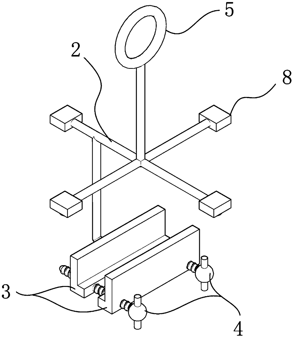
[0024] Please refer to figure 1 , figure 2 with image 3 , figure 1 It is a schematic diagram of the overall structure of a specific embodiment provided by the present invention; figure 2 for figure 1 A partial cross-sectional view of the structure shown; image 3 for figure 1 Schematic diagram of the structure of the fixed frame shown

[0025] In a specific embodiment provided by the present invention, the bulk mineral reaction equipment mainly inclu...


PUM


Abstract

The invention discloses a massive mineral reaction device. The device comprises a barrel body, a fixing frame, clamping plates and connectors, wherein the fixing frame is detachably arranged in the barrel body; a magnetic rotor is arranged in the barrel body and acts with a magnetic stirring device to realize medicine solution stirring; the clamping plates are connected through the connectors to form a massive mineral loading device; and the loading device is arranged at the bottom part of the fixing frame and is suspended in the barrel body. According to the massive mineral reaction device, the clamping plates and the connectors are adopted, and massive mineral in any shape can be clamped; and moreover, the surface of the massive mineral to be acted can be in complete contact with a medicine solution to the hilt, and thus the massive minerals can be completely reacted; and meanwhile, the fixing frame and the barrel body are made of organic glass, so that the corrosion of the medicinesolution to equipment can be minimized, and as a result, the reaction cost is decreased.

Description

technical field [0001] The invention relates to the technical field of mining production, in particular to a block mineral reaction equipment. Background technique [0002] When studying the mechanism of action of minerals and pharmaceuticals, it is often necessary to conduct contact angle tests, SECM / LEIS (micro-area electrochemical workstation) tests, TOF-SIMS (secondary time-of-flight mass spectrometers), atomic force microscopy and other tests. These tests usually require Blocky pure minerals are used as test objects. [0003] When preparing the test samples after the action of the ore block and the agent, it is necessary to soak the massive pure mineral in the agent solution. On the one hand, due to the small surface area of ​​the ore (compared to the particles under the same quality conditions), the reaction is slow; on the other hand, the ore is placed in a beaker and cannot be stirred by magnetic force. If magnetic stirring is used, the magnetic rotor will collide. ...

Claims


Application Information

Patent Timeline
IPC IPC(8): B01J19/00B01F13/08
CPCB01J19/0066B01F33/4532B01F33/45
Inventor 罗德强王洪彬张春李金林李有余桂华明
Owner PANGANG GRP MINING
Learn More