Mineral flotation system

A mineral flotation and flotation cell technology, applied in flotation, solid separation, etc., can solve the problems of insufficient collision between mineral particles to be recovered and air bubbles, and low flotation efficiency, so as to improve flotation efficiency and reduce the difficulty of collision , the effect of increasing the probability of collision

Active Publication Date: 2018-12-21
ANHUI UNIV OF SCI & TECH
View PDF10 Cites 2 Cited by
  • Summary
  • Abstract
  • Description
  • Claims
  • Application Information

AI Technical Summary

Problems solved by technology

[0003] When the existing flotation system is performing mineral flotation work, there are a large number of invalid collisions between the pulp material and the ai

Method used


Image

  • Mineral flotation system
  • Mineral flotation system

Examples


Embodiment Construction

[0030] In order to make the purpose, technical solutions and advantages of the present invention clearer, the present invention will be described in further detail below in conjunction with the accompanying drawings and embodiments. All other embodiments obtained below all belong to the protection scope of the present invention.

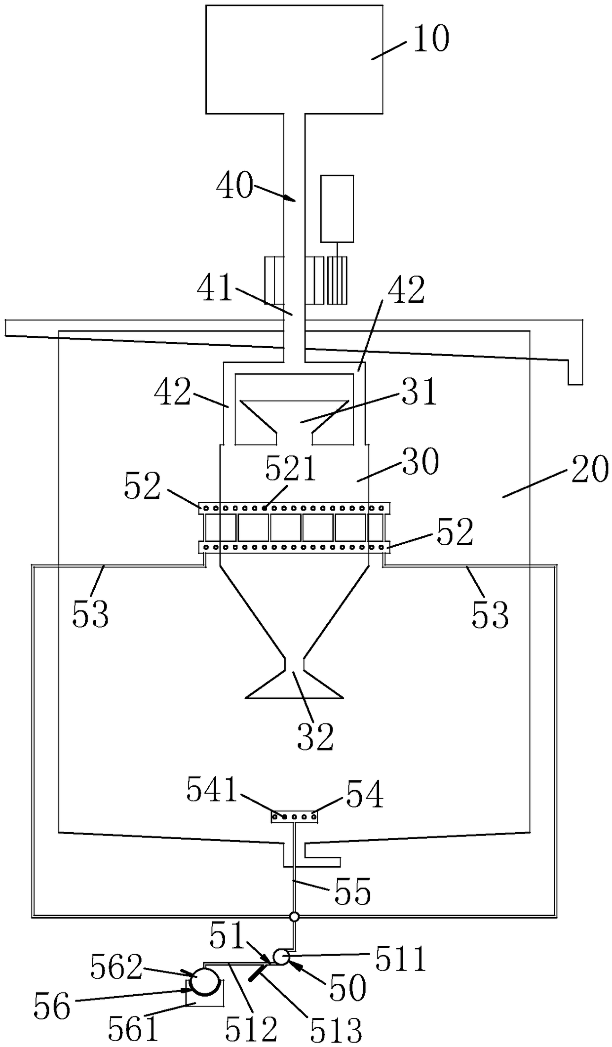
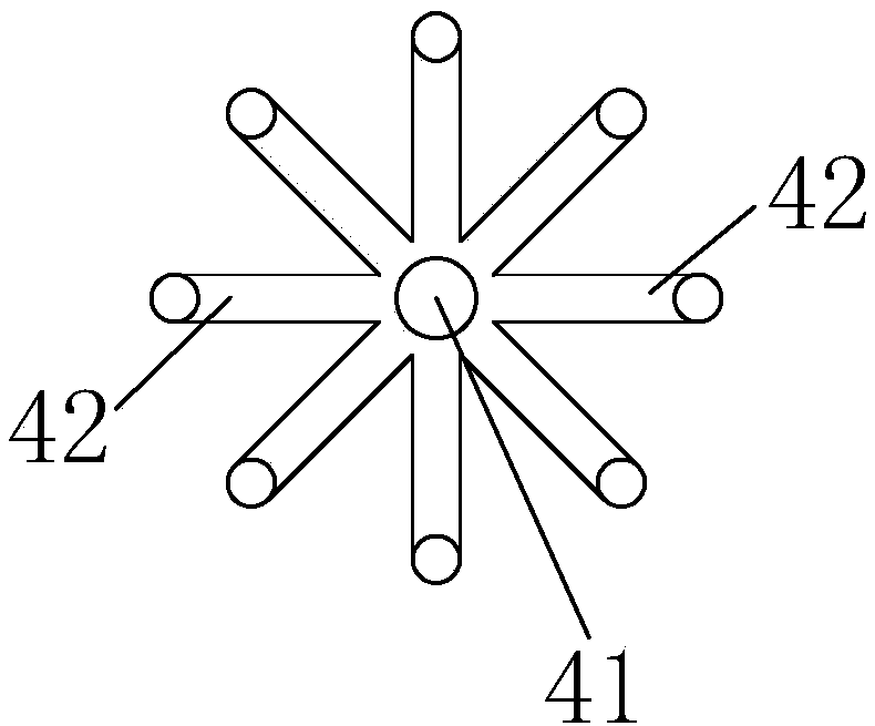
[0031] Such as figure 1 , 2 As shown, a mineral flotation system includes a rotatable pulp bucket 10, a flotation cell 20 communicated with the pulp bucket 10, and a rotatable rotary bucket 30 is set inside the flotation cell 20, the The rotary barrel 30 communicates with the pulp barrel 10 through a pipeline 40, and one end of the pipeline 40 connected to the rotary barrel 30 is located at the upper end of the barrel wall of the rotary barrel 30 or is arranged next to the barrel wall of the rotary barrel 30, so that the slurry The slurry mixed with the collector in the barrel 10 can enter the rotary barrel 30 tangentially or from top to bottom alo...


PUM


Abstract

The invention belongs to the technical field of mineral flotation, and particularly relates to a mineral flotation system. The device comprises a rotatable ore pulp barrel, a flotation groove communicated with the ore pulp barrel, a rotating barrel capable of rotating is arranged in the flotation groove in a sleeved mode, the rotating barrel is communicated with the ore pulp barrel through a pipeline, one end, connected with the rotating barrel, of the pipeline is located at the upper end of the barrel wall of the rotating barrel or close to the barrel wall of the rotating barrel, the rotatingbarrel and the ore pulp barrel rotate synchronously, the lower part of the rotating barrel is of a cone structure and is in a reduced diameter shape from top to bottom, an upper overflow port and a lower underflow port are formed in the upper end and the lower end of the rotating barrel respectively, the flotation groove is communicated with the ore pulp barrel through the rotating barrel and thepipeline; the system further comprises a bubble generation device, and the bubble generation device is communicated with the flotation groove. According to the mineral flotation system, the effectivecollision rate of the bubbles can be improved when the mineral flotation work is carried out, so that the collision probability between the bubbles and the mineral particles to be recovered is increased, and then the flotation efficiency is improved.

Description

technical field [0001] The invention belongs to the technical field of mineral flotation, in particular to a mineral flotation system. Background technique [0002] Froth flotation is a well-known method for separating crushed fine materials from slurry or suspension in water. The pellets that are expected to be recovered from the pulp can be treated with chemicals (collectors) to render them hydrophobic and a gas, usually air, mixed or sprayed into the pulp in the form of bubbles that come into contact with the hydrophobic pellets , carrying them to the surface of the slurry to form a stable layer of foam. The froth containing the buoyant particles is recovered as enrichment or flotation product, and various hydrophilic materials are left to sink into the slurry and then discharged or subjected to secondary flotation. [0003] When the existing flotation system is performing mineral flotation work, there are a large number of ineffective collisions between the pulp materi...

Claims


Application Information

Patent Timeline
IPC IPC(8): B03D1/24
CPCB03D1/24
Inventor 朱宏政徐文玉黄典强邵善敏李梦闪李甜王海楠
Owner ANHUI UNIV OF SCI & TECH
Why Eureka
Try Eureka