Method and apparatus for mixing fluids for particle agglomeration

a technology of mixing fluid and particle agglomeration, which is applied in the directions of auxillary pretreatment, separation processes, transportation and packaging, etc., can solve the problems of emitted small hazardous particles into the atmosphere, posing a significant danger to public health, and usually much less effective in filtering out small particles. , to achieve the effect of efficient agglomeration of particles, reducing pressure loss, and improving particle mixing

Inactive Publication Date: 2006-11-16
INDIGO TECH GRP PTY LTD
View PDF16 Cites 9 Cited by
  • Summary
  • Abstract
  • Description
  • Claims
  • Application Information

AI Technical Summary

Benefits of technology

[0039] The use of small scale turbulence is counterintuitive. Normally, it is desirable that the pressure drop in the gas stream be as low as possible. For this reason, known particle mixing systems normally use large scale turbulence. However, as mentioned above, these are inefficient. Small scale turbulence promotes better mixing of the particles, but results in significant pressure loss. The present invention employs small scale turbulence but only in a limited zone in each passage, thereby minimising pressure loss. The large scale turbulence in the fluid substream in each passage ensures that the particles in each substream pass through the zone and are subjected to mixing at particle scale.
[0040] The small scale turbulence may be in the form of vortices generated by sharp-edged vanes. Preferably, a multiplicity of small, low intensity vortices are used to fully entrain the individual fine particles and subject them to turbulent flow, thereby resulting in collisions and interactions between the particles, an

Problems solved by technology

Many industrial processes result in the emission of small hazardous particles into the atmosphere.
As these fine particles are able to enter the human respiratory system, they pose a significant danger to public health.
Although these methods are generally suitable for removing larger particles from air streams, they are usually much less effective in filtering out smaller particles, particularly PM2.5 particles.
For m

Method used


Image

  • Method and apparatus for mixing fluids for particle agglomeration
  • Method and apparatus for mixing fluids for particle agglomeration
  • Method and apparatus for mixing fluids for particle agglomeration

Examples


Embodiment Construction

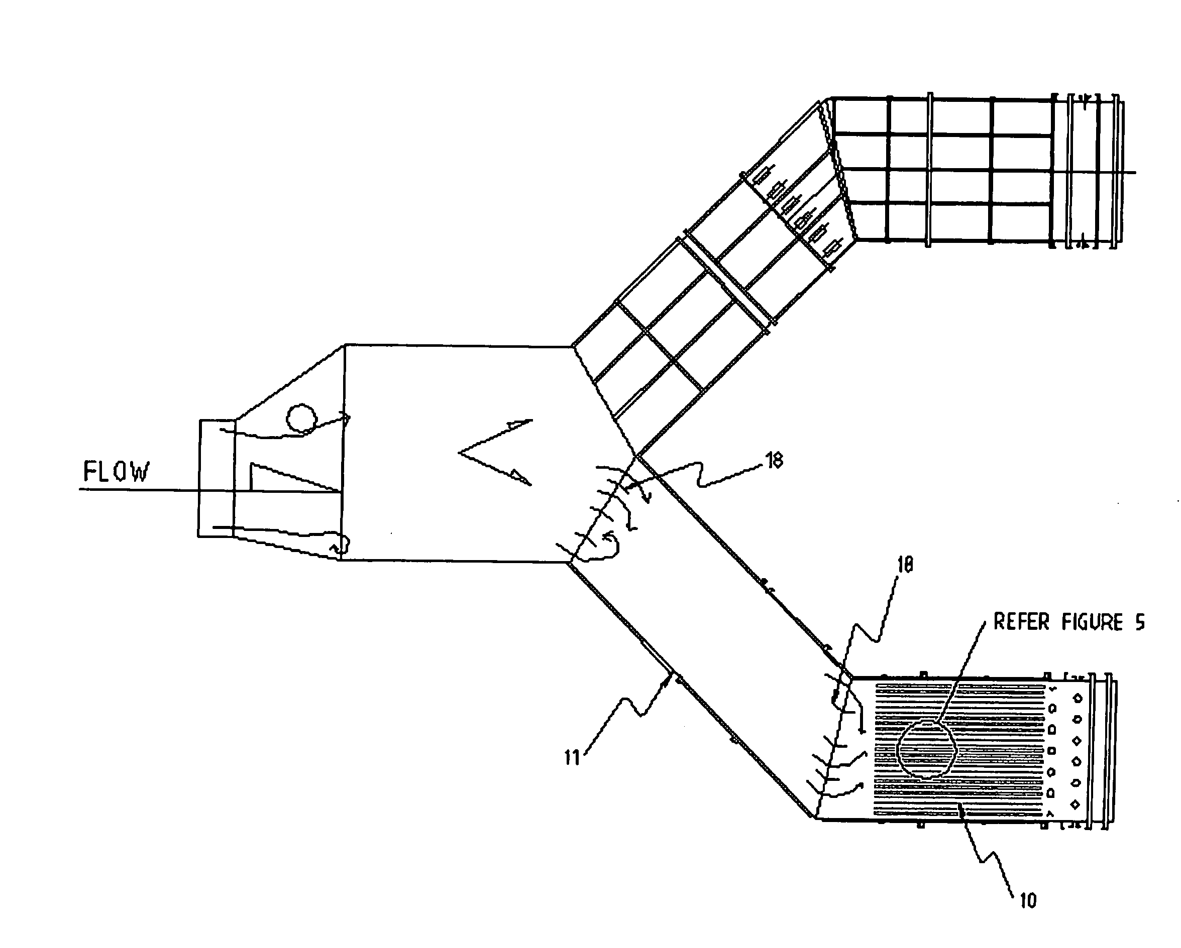
[0053] FIGS. 1 to 6 illustrate an aerodynamic agglomerator according to one embodiment of this invention. The agglomerator 10 is housed in a duct 11 which typically receives a flow of exhaust gas from an industrial process, as shown in FIG. 1.

[0054] The agglomerator 10 comprises a plurality of generally planar members, such as metal plates 12, which extend longitudinally in the duct 11 (i.e. in the direction of overall gas flow), and are spaced transversely across the whole width of the duct. Passages are formed between the plates 12, and the gas flow is divided into substreams flowing through respective passages. Although the plates 12 are mounted vertically as shown in FIG. 2, they can be arranged horizontally if desired. Moreover, the plates 12 need not be solid. Perforated plates can be used if desired.

[0055] Vane assemblies 13 are mounted between the plates 12. Each vane assembly 13 is located centrally in its respective passage between two adjacent plates 12, and extends par...


PUM

PropertyMeasurementUnit
Flow rateaaaaaaaaaa
Sizeaaaaaaaaaa
Widthaaaaaaaaaa

Abstract

An aerodynamic agglomerator (10) promotes mixing and agglomeration of pollutant particles in a gas stream, to facilitate the subsequent removal of the particles from the gas stream. The agglomerator (10) is mounted in a duct (11) through which the gas stream flows. The agglomerator (10) comprises a plurality of parallel plates (12) which extend in the overall direction of flow of the gas stream, and are spaced transversely across the width of the duct (11) to divide the duct into multiple parallel passages. The duct (11) is configured and/or has formations therein for creating large scale turbulence in the gas stream upstream of the passages. A vane assembly (13) is provided in each passage for generating a zone of small scale turbulence of such size and/or intensity that the pollutant particles are entrained in the turbulence. Each vane assembly (13) is located centrally relative to its respective passage and comprises a plurality of sharp-edged vanes (15) spaced successively in the overall direction of flow of the gas stream. The large scale turbulence in the substreams causes each substream to pass through the zone of small scale turbulence in its respective passage so that particles therein are subjected to the small scale turbulence.

Description

[0001] This invention relates generally to method and apparatus for mixing fluids for particle agglomeration. The invention is particularly, but not solely, suitable for use in pollution control to remove pollutant fine particles from air streams. [0002] In a preferred embodiment, the invention is directed to aerodynamic particle agglomeration in which particle scale turbulence is used to promote interactions and agglomeration of the particles, and thereby facilitate subsequent filtration or other removal of the particles from the air streams. [0003] This application claims priority from Australian patent applications nos. 2003902014 and 2004900593, the disclosures of which are incorporated herein by reference. BACKGROUND ART [0004] Many industrial processes result in the emission of small hazardous particles into the atmosphere. These particles often include very fine sub-micron particles of toxic compounds. As these fine particles are able to enter the human respiratory system, th...

Claims


Application Information

Patent Timeline
IPC IPC(8): B01F5/06B01D51/02B01F23/30B01J2/16
CPCB01D51/02B01F5/0618B01J2/16B01F2005/0635B01F2215/0431B01F5/0643B01F25/4316B01F25/43197B01F25/4322
Inventor TRUCE, RODNEY JOHNWILKINS, JOHN WALTER
Owner INDIGO TECH GRP PTY LTD
Why Eureka
Try Eureka