A device for cleaning dust on the surface of an instrument

A technology for cleaning devices and dust, applied in cleaning methods and utensils, chemical instruments and methods, and cleaning methods using tools, etc., can solve the problems of insufficient cleaning and time-consuming and other problems

Active Publication Date: 2021-04-27
江苏良玉激光新材料有限公司
View PDF4 Cites 0 Cited by
  • Summary
  • Abstract
  • Description
  • Claims
  • Application Information

AI Technical Summary

Problems solved by technology

[0003] In order to overcome the shortcomings of manual dust cleaning that takes a lot of time and is not thorough enough, the technical problem to be solved is: to provide a dust cleaning device on the surface of the instrument that saves time and cleans thoroughly

Method used


Image

  • A device for cleaning dust on the surface of an instrument
  • A device for cleaning dust on the surface of an instrument
  • A device for cleaning dust on the surface of an instrument

Examples


Embodiment 1

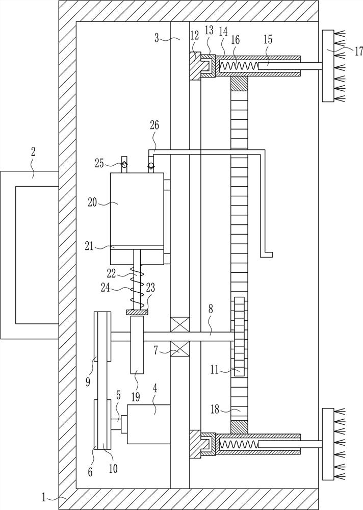
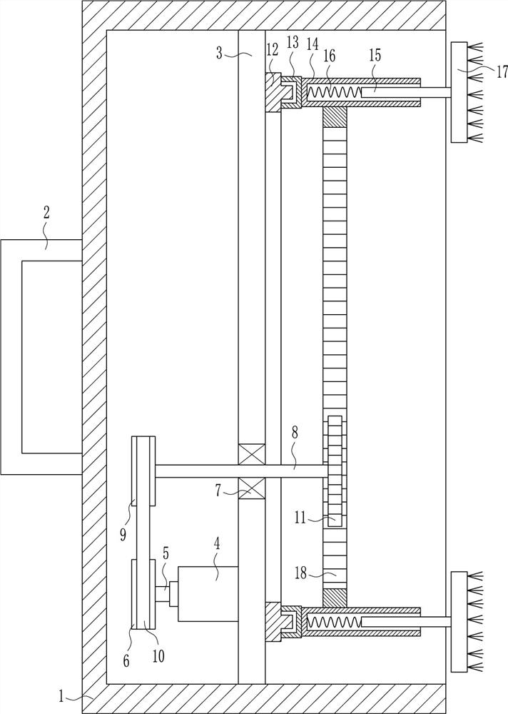
[0019] A device for cleaning dust on the surface of an instrument, such as Figure 1-3 As shown, it includes a frame body 1, a handle 2, a riser 3, a first motor 4, a first rotating shaft 5, a first pulley 6, a bearing seat 7, a second rotating shaft 8, a second pulley 9, a flat belt 10, the first A gear 11, an annular slide rail 12, a slide block 13, a sleeve 14, a first slide bar 15, a first spring 16, a hair brush 17 and an inner ring gear 18, and a handle 2 is installed in the middle part of the outer left side of the frame body 1, A riser 3 is installed in the middle of the frame body 1, a first motor 4 is installed on the lower part of the left side of the riser 3, a first rotating shaft 5 is installed on the output shaft of the first motor 4, and a first pulley is installed on the left end of the first rotating shaft 5 6. The lower part of the vertical plate 3 is embedded with a bearing seat 7, and the bearing in the bearing seat 7 is connected with a second rotating sh...

Embodiment 2

[0021] A device for cleaning dust on the surface of an instrument, such as Figure 1-3 As shown, it includes a frame body 1, a handle 2, a riser 3, a first motor 4, a first rotating shaft 5, a first pulley 6, a bearing seat 7, a second rotating shaft 8, a second pulley 9, a flat belt 10, the first A gear 11, an annular slide rail 12, a slide block 13, a sleeve 14, a first slide bar 15, a first spring 16, a brush 17 and an inner ring gear 18, and a handle 2 is installed in the middle part of the outer left side of the frame body 1, A riser 3 is installed in the middle of the frame body 1, a first motor 4 is installed on the lower part of the left side of the riser 3, a first rotating shaft 5 is installed on the output shaft of the first motor 4, and a first pulley is installed on the left end of the first rotating shaft 5 6. The lower part of the vertical plate 3 is embedded with a bearing seat 7, and the bearing in the bearing seat 7 is connected with a second rotating shaft 8...

Embodiment 3

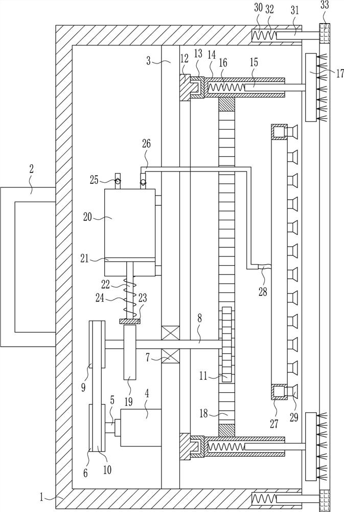
[0024]A device for cleaning dust on the surface of an instrument, such as Figure 1-3 As shown, it includes a frame body 1, a handle 2, a riser 3, a first motor 4, a first rotating shaft 5, a first pulley 6, a bearing seat 7, a second rotating shaft 8, a second pulley 9, a flat belt 10, the first A gear 11, an annular slide rail 12, a slide block 13, a sleeve 14, a first slide bar 15, a first spring 16, a hair brush 17 and an inner ring gear 18, and a handle 2 is installed in the middle part of the outer left side of the frame body 1, A riser 3 is installed in the middle of the frame body 1, a first motor 4 is installed on the lower part of the left side of the riser 3, a first rotating shaft 5 is installed on the output shaft of the first motor 4, and a first pulley is installed on the left end of the first rotating shaft 5 6. The lower part of the vertical plate 3 is embedded with a bearing seat 7, and the bearing in the bearing seat 7 is connected with a second rotating sha...


PUM


Abstract

The invention relates to a cleaning device, in particular to a dust cleaning device on the surface of an instrument. The technical problem to be solved is to provide a device for cleaning dust on the surface of an instrument that saves time and cleans up enough and thoroughly. The technical solution of the present invention is: a dust cleaning device on the surface of an instrument, including a frame body, a handle, a vertical plate, a first motor, etc.; A first motor is installed on the lower part of the left side. In the present invention, the first motor is used as the drive, and the inner ring gear is driven to rotate through the first gear, so that the brush can be driven to clean the dust on the surface of the instrument. A compression cylinder is also provided, and the cam drives the compression cylinder to extract air, and then sprays it to the The surface of the instrument, under the action of the second slide bar and the third spring, can make the rubber frame always contact with the surface of the shell of the instrument, so that the brush can be more stable during dust removal, and can be cleaned more thoroughly.

Description

technical field [0001] The invention relates to a cleaning device, in particular to a dust cleaning device on the surface of an instrument. Background technique [0002] The instrument has been used for a long time, and there will be a lot of dust on its surface. In order to facilitate the inspection of the instrument, it is necessary to clean the dust on the instrument. The existing ones usually hold a brush in one hand and a bucket in the other. It takes a lot of time to clean the dust on the outer surface of the instrument with a towel soaked in water, and when cleaning the dust on the instrument with a towel soaked in water, it is easy to make the dust stick to the instrument, resulting in cleaning problems. It is not thorough enough. In order to shorten the time for cleaning the dust on the instrument, the manual will use a hand-held vacuum cleaner to clean the dust on the instrument. When the vacuum cleaner sucks the dust, it is easy to make the dust in the distance fl...

Claims


Application Information

Patent Timeline
Patent Type & Authority Patents(China)
IPC IPC(8): B08B1/04B08B5/02B08B13/00
CPCB08B1/002B08B1/04B08B5/02B08B13/00
Inventor 吴均崇杨毓波肖祥瑞
Owner 江苏良玉激光新材料有限公司
Why Eureka
Try Eureka