Rock wool belt heat preservation fireproof composite board cutting device

A technology of cutting device and composite board, which is applied in the direction of large-scale fixed members, metal processing machine parts, metal processing, etc., can solve the problems of wasting manpower, affecting product quality, and low work efficiency, and achieves convenient operation, high degree of automation, and lightening The effect of work intensity

Inactive Publication Date: 2018-12-21
合肥神舟建筑集团有限公司
5 Cites 6 Cited by

AI-Extracted Technical Summary

Problems solved by technology

The existing cutting device for thermal insulation and fireproof composite board with rock wool tape needs to manually push the composite board forward after the first cutting, which not only...

Abstract

The invention discloses a rock wool belt heat preservation fireproof composite board cutting device. The rock wool belt heat preservation fireproof composite board cutting device comprises a supporting mechanism, a cutting mechanism and a pushing mechanism, wherein the supporting mechanism is composed of a base, a first supporting column, a first cutting table, a second cutting table and a secondsupporting column, the cutting mechanism is composed of a first motor, a guide rail, a first sliding block, a threaded block, a first hydraulic telescopic rod, a second motor and a cutter, the pushingmechanism is composed of a pushing plate, a second hydraulic telescopic rod, a second sliding block and a third hydraulic telescopic rod, the first cutting table and the second cutting table are located at the same height, the first sliding block is connected with the guide rail in a sliding mode, the threaded block is in threaded connection with the rotating shaft, the second motor is fixedly connected to the lower end of the first hydraulic telescopic rod, an output shaft of the second motor is fixedly connected with the cutter, the pushing plate is in a U shape, the second sliding block isin sliding connection with the base, and the second sliding block is fixedly connected with the third hydraulic telescopic rod. According to the rock wool belt heat preservation fireproof composite board cutting device, the operation is convenient, the automation degree is high, the labor resources are saved, the working intensity of workers is relieved, and the product quality is guaranteed.

Application Domain

Large fixed membersMetal working apparatus

Technology Topic

WoolEngineering +2

Image

  • Rock wool belt heat preservation fireproof composite board cutting device
  • Rock wool belt heat preservation fireproof composite board cutting device
  • Rock wool belt heat preservation fireproof composite board cutting device

Examples

  • Experimental program(1)

Example Embodiment

[0018] The technical solution of this patent will be described in further detail below in conjunction with specific embodiments.
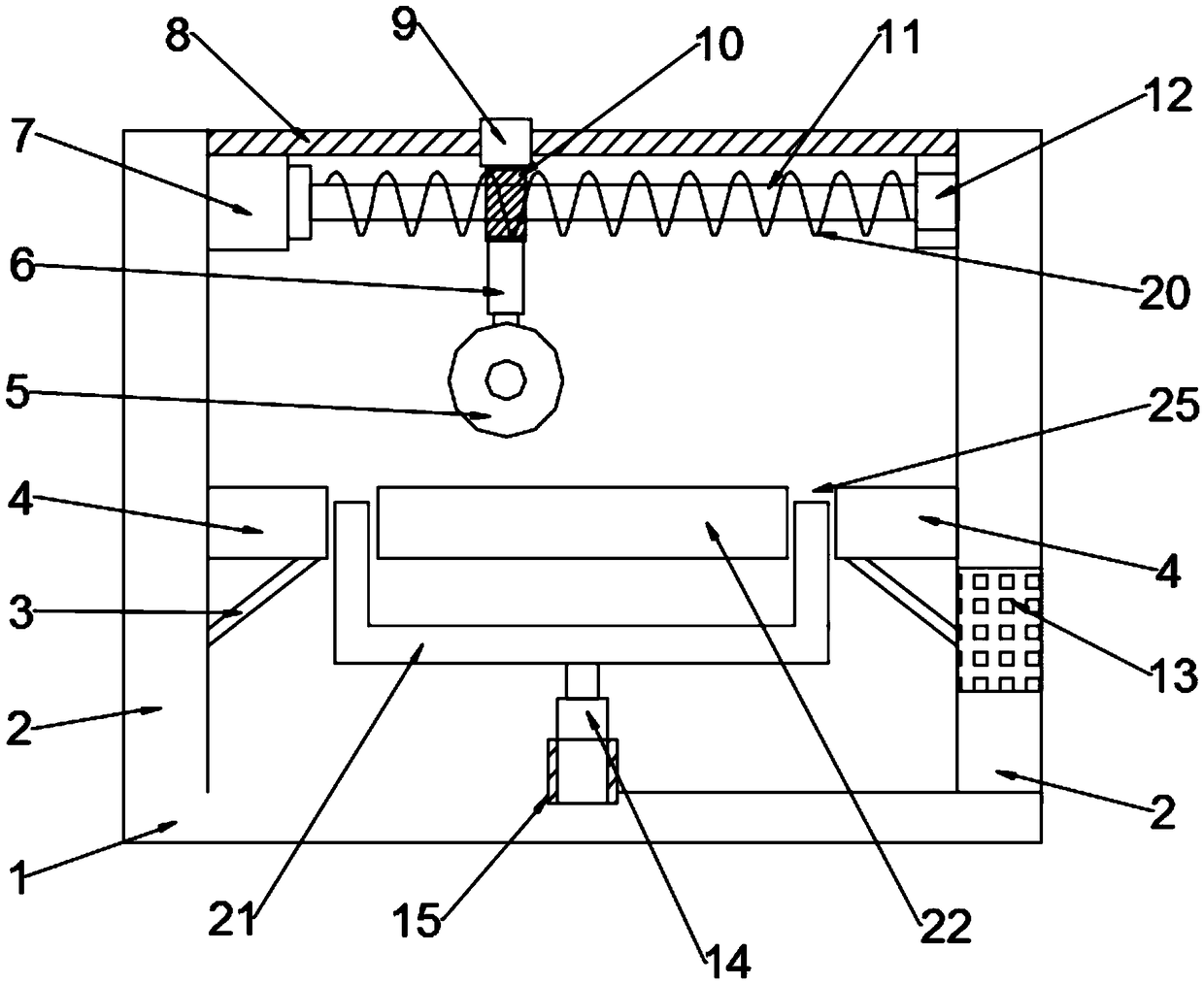
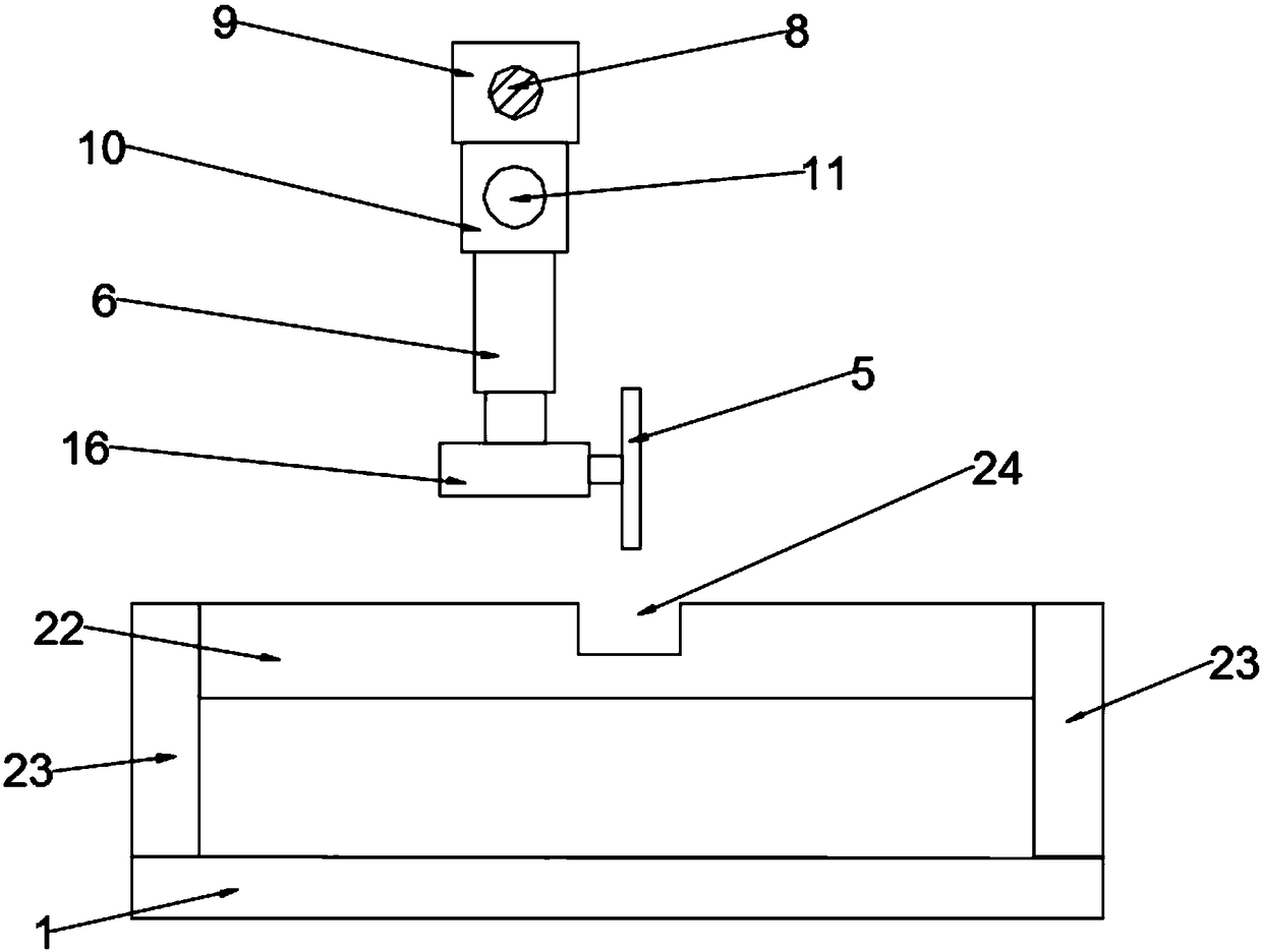
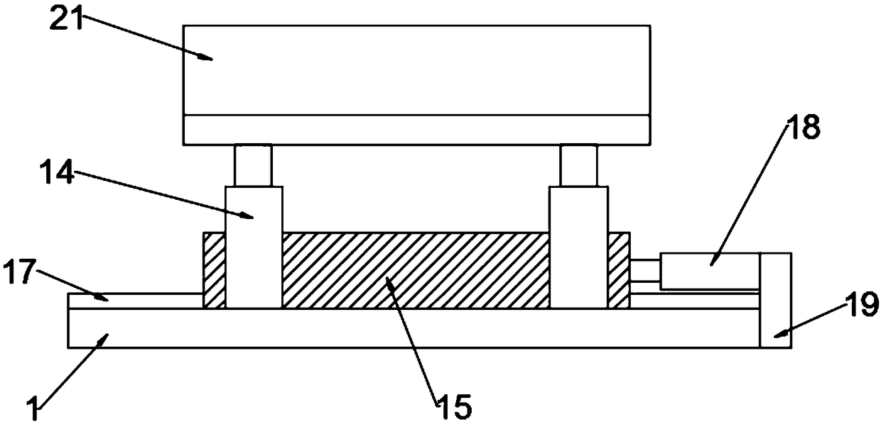
[0019] See Figure 1-3 , A rock wool belt thermal insulation and fireproof composite board cutting device, comprising a supporting mechanism, a cutting mechanism and a pushing mechanism; the cutting mechanism is located above the supporting mechanism, and the pushing mechanism is located below the supporting mechanism.
[0020] The supporting mechanism is composed of base 1, supporting column 1, cutting table 4, cutting table 2 22, and supporting column 2 23; the supporting column 1 is installed on the left and right ends of the base 1, and the side of the supporting column 2 is close to the middle There is a cutting table 4, the lower end of the cutting table 4 is fixedly connected with a supporting inclined rod 3, and the lower end of the supporting inclined rod 3 is fixedly connected to the side of the supporting column 2; the supporting column 23 is installed on the base 1 At the front and rear ends, the upper ends of the supporting columns 23 are fixedly connected to the cutting table 22; the cutting table 4 and the cutting table 22 are at the same height, and the cutting table 4 and the cutting table 22 are provided with a slot 24. The slot 24 can be It is convenient to cut the composite board and store the cut chips; a reserved space 25 is provided between the cutting table 4 and the cutting table 22.
[0021] The cutting mechanism is composed of a motor 7, a guide rail 8, a slider 9, a threaded block 10, a first hydraulic telescopic rod 6, a motor 2 16 and a cutter 5; the motor 7 is fixedly connected to the side wall of the support column 2 , The output shaft of the motor 7 is fixedly connected with the rotating shaft 11, the rotating shaft 11 is provided with a thread 20, and the right end of the rotating shaft 11 is connected with the supporting column 1-2 through the bearing 12; between the top ends of the two supporting columns 1-2 The guide rail 8 is fixedly connected, and the sliding block 9 is slidably connected with the guide rail 8; the lower end of the sliding block 9 is fixedly connected with a threaded block 10, and the threaded block 10 is provided with internal threads for use with the thread 20, and the threaded block 10 is threaded with the rotating shaft 11 Connection; the first hydraulic telescopic rod 6 is fixedly connected to the lower end of the threaded block 10, the lower end of the first hydraulic telescopic rod 6 is fixedly connected to the motor two 16, the output shaft of the motor two 16 is fixedly connected with the cutter 5; the motor one 7, the motor two Both 16 and the first hydraulic telescopic rod 6 are electrically connected to the control panel 13.
[0022] The pushing mechanism is composed of a pushing plate 21, a second hydraulic telescopic rod 14, a sliding block 15 and a third hydraulic telescopic rod 18. The pushing plate 21 is U-shaped, and the pushing plate 21 is fixedly installed on the second hydraulic telescopic rod 14. , The second hydraulic telescopic rod 14 can lift the push plate 21 and pass through the reserved space 25; the second hydraulic telescopic rod 14 is fixedly installed on the second slide block 15, and the second slide block 15 is slidably connected to the base 1 through the slide groove 17 ; The front end of the slider two 15 is fixedly connected with the third hydraulic telescopic rod 18, the end of the third hydraulic telescopic rod 18 away from the slider two 15 is fixedly connected with the side plate 19, and the side plate 19 is fixedly installed at the front end of the base 1, so The sliding block two 15, the push plate 21 and the second hydraulic telescopic rod 14 can slide back and forth on the bottom plate 1; the second hydraulic telescopic rod 14 and the third hydraulic telescopic rod 18 are all electrically connected to the control panel 13.
[0023] The working principle of the present invention is: firstly, the composite sheet is placed on the cutting table 4 and the cutting table 2 22, and the second hydraulic telescopic rod 14 is controlled by the control panel 13 to expand and drive the push plate 21 to rise from the reserved space 25 and support Lift the composite plate so that the bottom surface of the composite plate does not touch the cutting table 1 4 and the cutting table 2 22, and then control the third hydraulic telescopic rod 18 to extend and drive the slider 2 15, the second hydraulic telescopic rod 14 and the push plate 21 to slide back and forth. In this way, the friction between the bottom surface of the composite sheet and the cutting table 4 and the cutting table 22 is avoided; after the composite sheet is moved to a suitable position, the second hydraulic telescopic rod 14 is controlled through the control panel 13 to lower the composite sheet to the cutting On the table one 4 and the cutting table two 22, the motor one 7 is turned on through the control panel 13 to drive the rotating shaft 11 to rotate. Because the sliding block nine is slidably connected with the guide rail 8 and the screw block 10 is threaded with the rotating shaft 11, the rotating shaft 11 Rotation will drive the slider 9, the threaded block 10, the first hydraulic telescopic rod 6 and the cutter 5 to move left and right; then turn on the motor two 16 through the control panel 13 to drive the cutter 5 to rotate, and finally control the first hydraulic telescopic rod 6 to expand and drive the motor The second 16 and the cutter 5 are lowered, so that the motor two 16 and the cutter 5 can move up and down to cut the composite sheet; when the first cutting is completed, the second hydraulic telescopic rod 14 and the third hydraulic telescopic rod 18 can be used. Lift the composite sheet and move it back to move to the next cutting position for the next cutting.
[0024] The preferred embodiments of this patent are described in detail above, but this patent is not limited to the above embodiments. It can also be made without departing from the purpose of this patent within the scope of knowledge possessed by those of ordinary skill in the art. Various changes.

PUM

no PUM

Description & Claims & Application Information

We can also present the details of the Description, Claims and Application information to help users get a comprehensive understanding of the technical details of the patent, such as background art, summary of invention, brief description of drawings, description of embodiments, and other original content. On the other hand, users can also determine the specific scope of protection of the technology through the list of claims; as well as understand the changes in the life cycle of the technology with the presentation of the patent timeline. Login to view more.

Similar technology patents

Laser radar optical system with optical axis calibrating function and optical axis calibrating method

InactiveCN102353950AOptical axis alignment with high precisioneasy to operate
Owner:INST OF APPLIED ELECTRONICS CHINA ACAD OF ENG PHYSICS +1

Defrosting control method and device

ActiveCN104807132Aeasy to operateDefrost is reasonable
Owner:GREE ELECTRIC APPLIANCES INC OF ZHUHAI

Classification and recommendation of technical efficacy words

  • easy to operate
  • high degree of automation

Lancet device

InactiveUS7303573B2inexpensively mass-producedeasy to operate
Owner:ABBOTT DIABETES CARE INC

Rapid and non-invasive optical detection of internal bleeding

InactiveUS20050065436A1easy to operaterapid and accurate result
Owner:HO WINSTON ZONH +2

High-fineness urban three-dimensional modeling method

Owner:星际空间(天津)科技发展有限公司

Bolt machining all-in-one machine

Owner:ANHUI LIUFANG ZHONGLIAN MECHANICAL SHARE
Why Eureka
Try Eureka