Control method of multi-cavity steel component assembling and positioning mechanism

A positioning mechanism and control method technology, applied in auxiliary devices, manufacturing tools, auxiliary welding equipment, etc., can solve problems such as large positioning deviations, achieve the effects of preventing false welding, compact structure, and shortening the processing period

Active Publication Date: 2018-12-21
浙江东南网架股份有限公司
View PDF8 Cites 0 Cited by
  • Summary
  • Abstract
  • Description
  • Claims
  • Application Information

AI Technical Summary

Problems solved by technology

[0003] The invention mainly solves the problem of large positioning deviation in the prior art, and provides a control method for the assembly and positioning mechanism of multi-cavity steel components, which has the advantages of compact structure, accurate positioning and integrated assembly and welding, and improves the multi-cavity The processing and welding accuracy of body steel components shorten the processing period

Method used


Image

  • Control method of multi-cavity steel component assembling and positioning mechanism
  • Control method of multi-cavity steel component assembling and positioning mechanism
  • Control method of multi-cavity steel component assembling and positioning mechanism

Examples


Embodiment

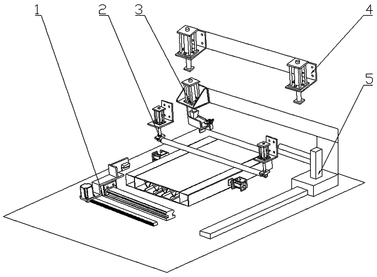
[0032] Example: such as Figure 1-5 As shown, a control method of a multi-cavity steel member assembly positioning mechanism is as follows:

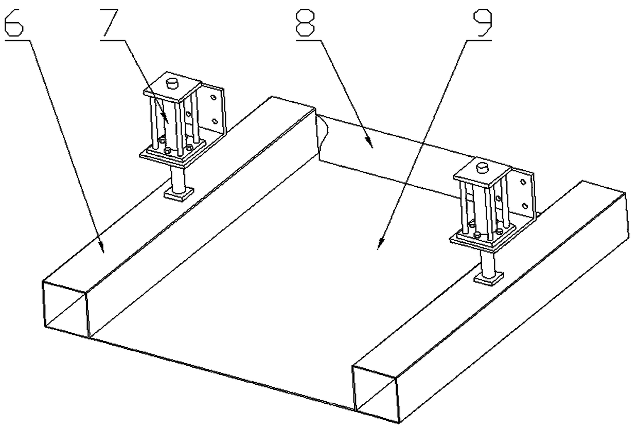
[0033] Step 1: hoist the bottom plate 9 onto the working platform by driving, and at the same time place the square tubes 6 on both sides on the working platform to be in close contact with the sides of the bottom plate 9, and then use the square tube to position and assemble the component 4 and the upper tube to position the pressing piece 7 The other side tube is compressed and positioned.

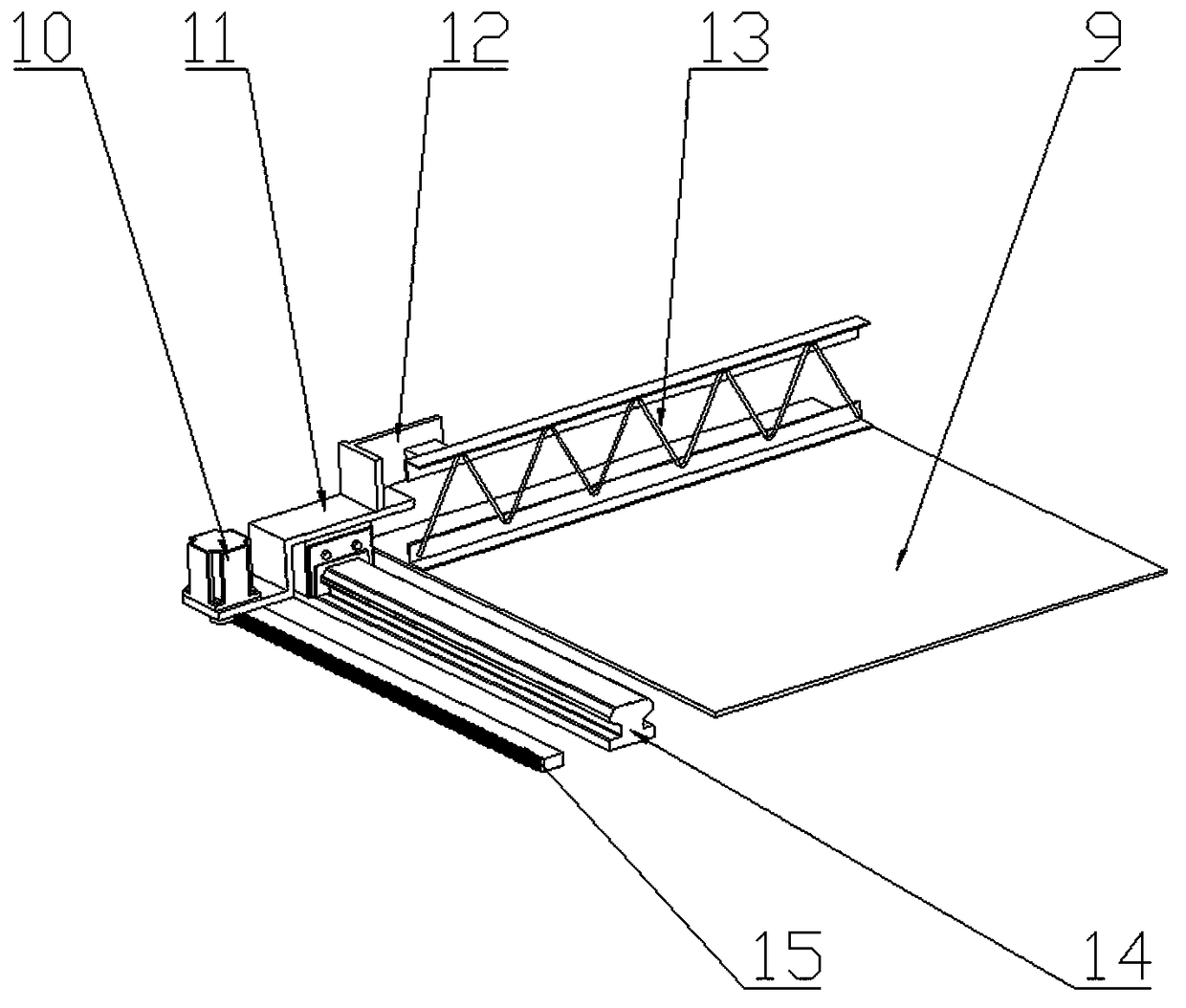
[0034] Step 2: hoist the steel bar truss 13 on the positioned bottom plate 9, and provide preliminary positioning assistance to the steel bar truss 13 through the steel bar truss assembly and positioning component 1. The rack guide rail 15 drives the end preliminary positioning member 11 to move laterally on the end preliminary positioning member guide rail 14 to assist in positioning the steel bar truss.

[0035] The third step: the positioning ...


PUM


Abstract

The invention relates to a control method of a multi-cavity steel component assembling and positioning mechanism, and belongs to the technical field of multi-cavity steel component assembling equipment. The mechanism comprises a square tube positioning and pressing frame. Two ends of the square tube positioning and pressing frame are provided with square tube positioning and pressing pieces connected with the square tube positioning and pressing frame in a displacement mode. An electromagnet is arranged at a front end of an end primary positioning piece. A lower end of the end primary positioning piece is provided with an end primary positioning piece guide rail which is in sliding connection with the end primary positioning piece. A driving motor is arranged at the rear end of the end primary positioning piece. A rack guide rail parallel to the end primary positioning piece guide rail is arranged below the driving motor. The rack guide rail is movably engaged with the drive motor. Thelower end of a displacement cylinder is provided with a lock pressing piece which is movably contacted. Two ends of a pressing roller are provided with bearing seats which are movably sleeved with the pressing roller. Pressing cylinders are arranged on the bearing seats. According to the control method of the multi-cavity steel component assembling and positioning mechanism, the method has the advantages of being compact in structure, accurate in positioning and integrated in assembling and welding; and the machining precision of the multi-cavity steel components is improved, and the machining period is shortened.

Description

technical field [0001] The invention relates to the technical field of multi-cavity steel component assembly equipment, in particular to a control method for a multi-cavity steel component assembly positioning mechanism. Background technique [0002] The cavity steel member is composed of a top plate, a bottom plate, steel trusses and square tubes on both sides, and the square tubes and steel trusses are welded to the bottom plate and the top plate respectively. Fixing by manual fixtures and manual measurement have the problems of low accuracy and large errors, and the quality stability of multi-cavity steel components in the process of assembly and welding is poor. When batch production is required, the method of manual processing cannot improve the sales volume of the product. The assembly of multi-cavity steel components is carried out on a special assembly machine for multi-cavity steel components to achieve an increase in production. How to achieve the verticality requ...

Claims


Application Information

Patent Timeline
Patent Type & Authority Applications(China)
IPC IPC(8): B23K37/04
CPCB23K37/0443
Inventor 周观根刘贵旺张润王飞飞王观军谢董恩沈柏清
Owner 浙江东南网架股份有限公司
Why Eureka
Try Eureka