Cement component vibrating table

A vibrating table and component technology, used in ceramic molding machines, manufacturing tools, etc., can solve the problems of weakening the vibration effect, reducing production efficiency, increasing production costs, etc., and achieving the effect of improving time-consuming and laborious, improving compactness and improving stability.

Inactive Publication Date: 2018-12-21
浙江南洋水泥制品有限公司
View PDF5 Cites 3 Cited by
  • Summary
  • Abstract
  • Description
  • Claims
  • Application Information

AI Technical Summary

Problems solved by technology

[0002] At present, in the field of road or engineering construction, cement components are often used. Now the cement components are mostly prepared by prefabricated molds and assembled during use. This method greatly improves the installation efficiency. In order to increase the compactness of cement prefabricated structures, usually Both need to vibrate the cement construction. According to different usage requirements, the cement construction is in various styles, such as round, diamond, square, etc., which requires a variety of corresponding cement construction molds. Because the cement construction molds are diverse Therefore, it is necessary to match different vibrating tables during actual vibration. There is no vibrating table suitable for molds of various shapes in the prior art. As a result, various types of vibrating tables need to be purchased, which increases production costs and reduces In order to reduce the production efficiency, it is time-consuming and labor-intensive, and when the vibration generated by the vibrating table is generally transmitted to the mold, the vibration effect is greatly weakened, resulting in poor vibration efficiency. In order to solve the above problems, we propose a vibrating table for cement components

Method used


Image

  • Cement component vibrating table
  • Cement component vibrating table
  • Cement component vibrating table

Examples


Embodiment Construction

[0024] In order to make the technical means, creative features, goals and effects achieved by the present invention easy to understand, the present invention will be further described below in conjunction with specific embodiments.

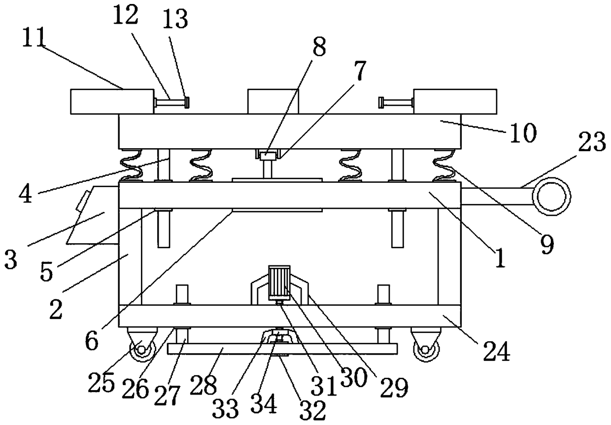
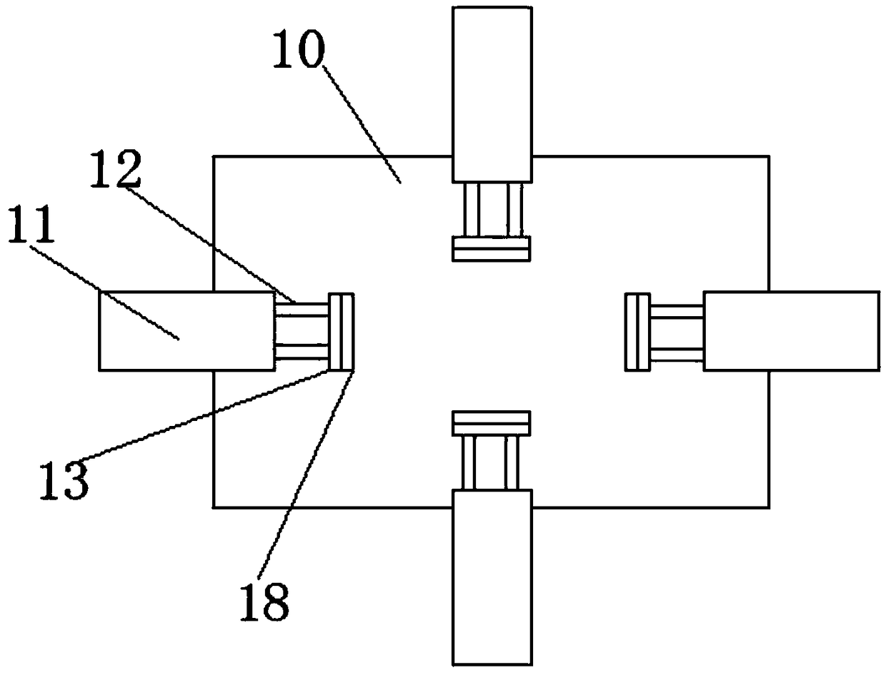
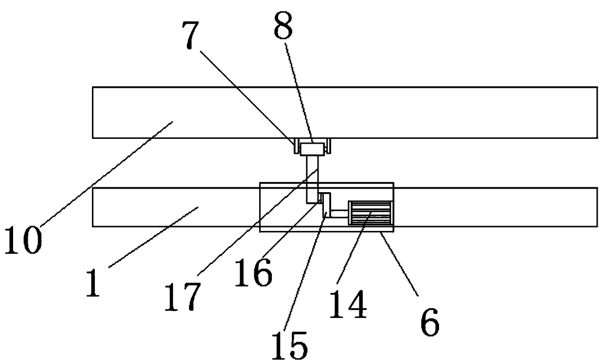
[0025] see Figure 1-5 , the present invention provides a technical solution: a vibrating table for cement components, including a platform 1, the four corners of the bottom end of the platform 1 are fixed with support columns 2, and the bottom ends of the support columns 2 are connected to the top of the base plate 24 , the middle part of the top of the platen 1 is provided with a hollow groove 6, the inner wall of the hollow groove 6 is equipped with a first motor 14, and the motor shaft of the first motor 14 is connected to one end on which the first guide rod 15 is fixed, so A turntable 16 is installed on the outer wall of the first guide rod 15, the first guide rod 15 is connected with the second guide rod 17 through the turntable 16, the oth...


PUM


Abstract

The invention discloses a cement component vibrating table. The cement component vibrating table comprises a table board, wherein the four corners of the bottom end of the table board are fixedly equipped with supporting columns; the bottom ends of the supporting columns are connected with the top end of a base plate; the middle part of the top end of the table board is equipped with a hollow slot; the inner wall of the hollow slot is equipped with a first motor; the motor shaft of the first motor is connected with one end fixedly equipped with a first guide rod; a rotary disc is mounted on the outer wall of the first guide rod; the first guide rod is connected with a second guide rod through a rotary disc; the other end of the second guide rod is connected with a rotary shaft; the rotaryshaft is mounted inside a fixed shaft frame; and the other end of the fixed shaft frame is connected with the bottom end of the vibrating table. According to the cement component vibrating table disclosed by the invention, the table board is connected with the vibrating table through a plurality of groups of springs, the first motor is connected with the second guide rod through the rotary disc via the first guide rod, and the second guide rod is connected with a rotary shaft in the fixed shaft frame, so that force for swinging the vibrating table up and down is provided, strong vibrations aregenerated and are directly transmitted onto the vibrating table in a facilitated mode, and compactness of a cement mould is improved.

Description

technical field [0001] The invention relates to a vibration table, in particular to a cement component vibration table. Background technique [0002] At present, in the field of road or engineering construction, cement components are often used. Now the cement components are mostly prepared by prefabricated molds and assembled during use. This method greatly improves the installation efficiency. In order to increase the compactness of cement prefabricated structures, usually Both need to vibrate the cement construction. According to different usage requirements, the cement construction is in various styles, such as round, diamond, square, etc., which requires a variety of corresponding cement construction molds. Because the cement construction molds are diverse Therefore, it is necessary to match different vibrating tables during actual vibration. There is no vibrating table suitable for molds of various shapes in the prior art. As a result, various types of vibrating tables...

Claims


Application Information

Patent Timeline
Patent Type & Authority Applications(China)
IPC IPC(8): B28B1/087
CPCB28B1/0873
Inventor 蔡忠华
Owner 浙江南洋水泥制品有限公司
Why Eureka
Try Eureka