Blowing needle mechanism for single blowing hole of blowing mold

A technology of blowing holes and blowing molds, which is applied in the field of blowing needles for blowing molds, which can solve problems such as troublesome installation and maintenance, reduced use stability, and increased product costs, so as to achieve low maintenance costs, prevent heat concentration, reduce volumetric effect

Active Publication Date: 2018-12-21
NINGBO FANGZHENG TOOL
View PDF4 Cites 1 Cited by
  • Summary
  • Abstract
  • Description
  • Claims
  • Application Information

AI Technical Summary

Problems solved by technology

[0003] At present, the product structure in the blow molding mold has only one port. In the blow molding process, an additional air outlet needs to be installed on the product, which can lead out the gas in the product during molding to prevent product defects caused by high-temperature gas concentration and excessive air pressure. After the blow molding is completed, the air outlet is blocked, but there are the following problems after this operation: first, the air outlet is blocked to prolong the production cycle, and also increases the probability of leakage, resulting in an increase in product cost and a decrease in use stability; The air return part is set on the side of the blowing needle mechanism, and is linked with the blowing needle mechanism, and the cylinder that pushes the blowing needle mechanism is larger, resulting in a larger overall volume, more parts, more troublesome installation and maintenance, and higher maintenance costs. high

Method used


Image

  • Blowing needle mechanism for single blowing hole of blowing mold
  • Blowing needle mechanism for single blowing hole of blowing mold
  • Blowing needle mechanism for single blowing hole of blowing mold

Examples


Embodiment 1

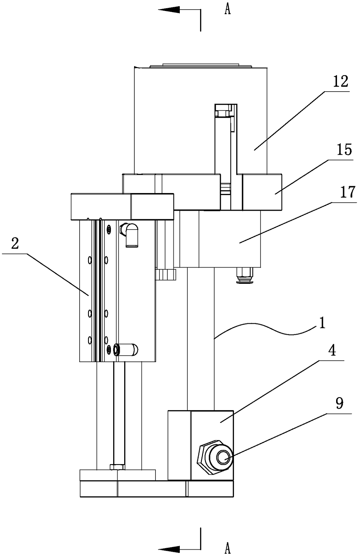
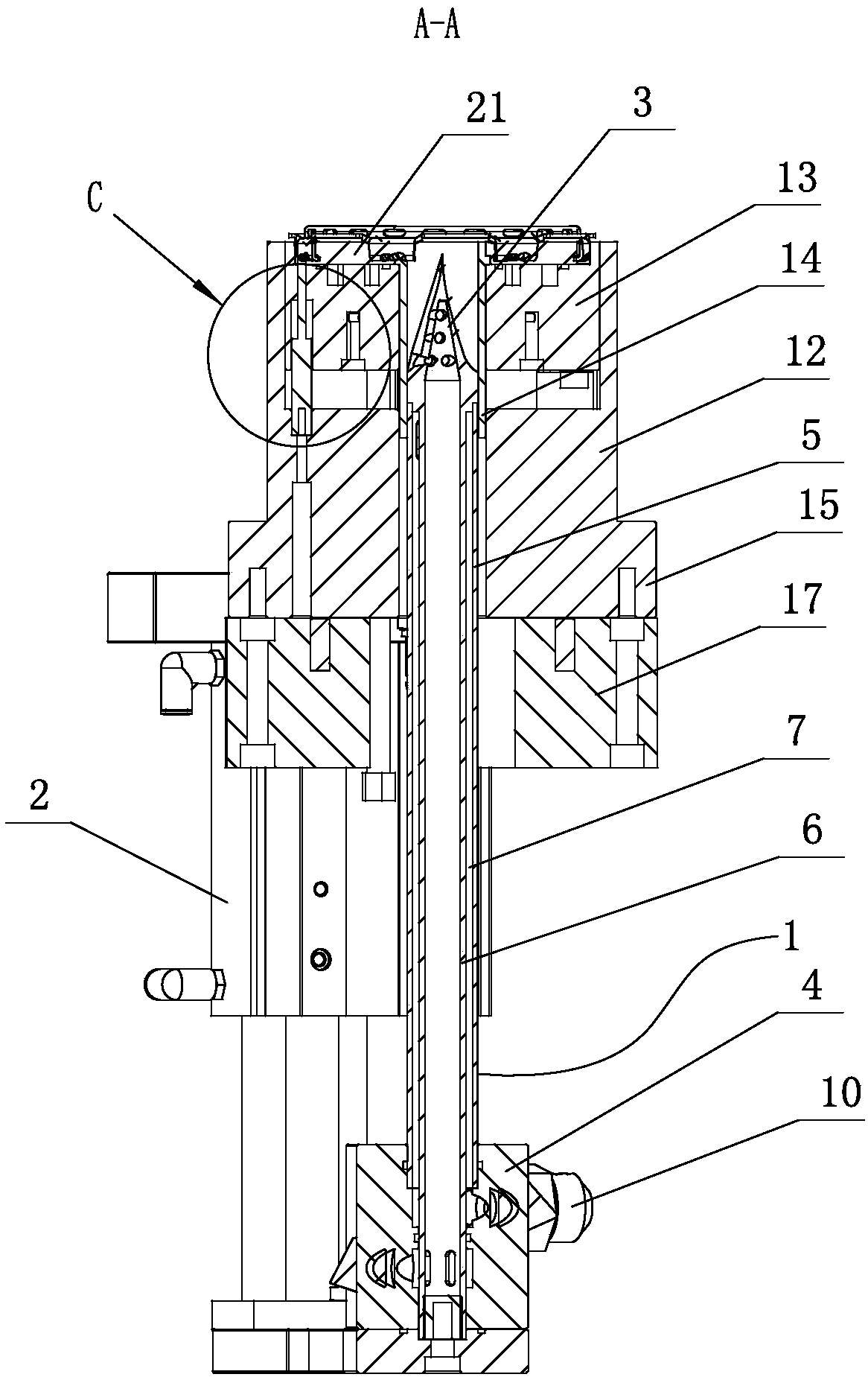
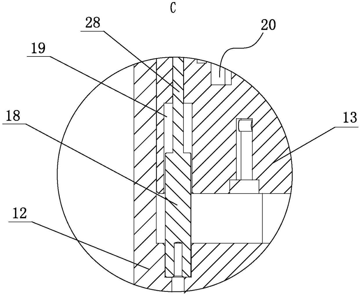
[0029] combine Figure 1-10, a blowing needle mechanism for a single blowing hole in a blow mold, which includes a blowing needle 1 connected to an air source, a push-pull cylinder 2 fixed on a mold base, and a blowing needle guide mechanism (of course also including other parts, but due to lack of It relates to the invention point of the present invention, so it will not be repeated here), the piston rod of the push-pull cylinder 2 is connected to the blowing needle 1, and the blowing needle 1 includes a needle head 3, a needle body and a needle seat 4; the needle body Including an outer tube 5 and an inner tube 6, the needle seat 4 is fixedly connected with the piston rod of the push-pull cylinder 2 through a connecting plate, the inner tube 6 is located in the outer tube 5, and the axis of the inner tube 6 is at the same axis as the outer tube 5 On a straight line, the inner wall of the outer tube 5 and the outer wall of the inner tube 6 form a channel 7; the upper end of t...

Embodiment 2

[0038] A blowing needle mechanism for a single blowing hole in a blow mold, which includes a blowing needle 1 connected to an air source, a push-pull cylinder 2 fixed on a mold base, and a blowing needle guide mechanism (of course also includes other parts, but since it is not involved Invention point created by the present invention, so no more details here), the piston rod of the push-pull cylinder 2 is connected with the blowing needle 1, and the blowing needle 1 includes a needle head 3, a needle body and a needle seat 4; the needle body includes The outer tube 5 and the inner tube 6, the needle seat 4 is fixedly connected with the piston rod of the push-pull cylinder 2 through the connecting plate, the inner tube 6 is located in the outer tube 5, and the axis of the inner tube 6 is on the same line as the axis of the outer tube 5 Above, the inner wall of the outer tube 5 and the outer wall of the inner tube 6 form a channel 7; the upper end of the inner tube 6 is connected...


PUM


Abstract

A blowing needle mechanism for a single blowing hole of a blowing mold comprises a blowing needle (1) connected with an air source, a push-pull air cylinder (2) fixed on a mold rack and a blowing needle guide mechanism, wherein a needle body comprises an outer pipe (5) and an inner pipe (6); the inner pipe (6) is located in the outer pipe (5); the inner wall of the outer pipe (5) and the outer wall of the inner pipe (6) form a channel (7); the upper end of the inner pipe (6) is connected and communicated with a needle head (3); the upper end of the outer pipe (5) is hermetically connected withthe needle head (3); at least one air hole (8) is formed in the outer peripheral surface of the upper end of the outer pipe (5); the lower end of the outer pipe (5) is connected with a needle seat (4); a first pipe connector (9) is communicated with the inner pipe (5); a second pipe connector (10) is communicated with the channel (7); and a plurality of air blowing holes (11) is formed in the needle head (3). Compared with the prior art, the blowing needle mechanism has the characteristics that the volume is relatively small, the production cycle can be shortened, the preparation cost is relatively low and the maintenance is relatively simple and convenient.

Description

technical field [0001] The invention relates to the technical field of blowing needles for blow molds, in particular to a blowing needle mechanism for a single blowing hole of a blow mold. Background technique [0002] Blow molding mainly refers to hollow blow molding (also known as blow molding), which is a method of blowing a hot-melt parison closed in a mold to form a hollow product by means of gas pressure. It is the third most commonly used plastic processing method, and at the same time It is also a fast-growing plastic molding method. The mold used for blow molding only has a female mold (concave mold). Compared with injection molding, the cost of equipment is lower, the adaptability is stronger, the formability is good (such as low stress), and products with complex undulating curves (shape) can be formed. . [0003] At present, the product structure in the blow molding mold has only one port. In the blow molding process, an additional air outlet needs to be instal...

Claims


Application Information

Patent Timeline
Patent Type & Authority Applications(China)
IPC IPC(8): B29C49/60B29C49/64
CPCB29C49/60B29C49/64
Inventor 方永杰陆鑫鑫程苗张修恩王锦浪程利波魏一辉陈聪蒋明杰薛乾东葛小翔周华民
Owner NINGBO FANGZHENG TOOL
Why Eureka
Try Eureka