Clip type feeding mechanism

A clip-type, tray technology, applied in conveyors, mechanical conveyors, conveyor objects, etc., can solve the problems of discontinuous feeding and low efficiency, and achieve the effect of reducing waiting time and improving work efficiency.

Pending Publication Date: 2018-12-21
SUZHOU RS TECH
View PDF5 Cites 7 Cited by
  • Summary
  • Abstract
  • Description
  • Claims
  • Application Information

AI Technical Summary

Problems solved by technology

[0005] Therefore, the technical problem to be solved by the present invention is to overcome the defect of low feeding efficiency of the automatic feeding mechanism in the prior art, so as to provide a material tray that can lift, feed, and carry the tray while loading and unloading the tray. clip-type feeding mechanism

Method used


Image

  • Clip type feeding mechanism
  • Clip type feeding mechanism
  • Clip type feeding mechanism

Examples


Embodiment 1

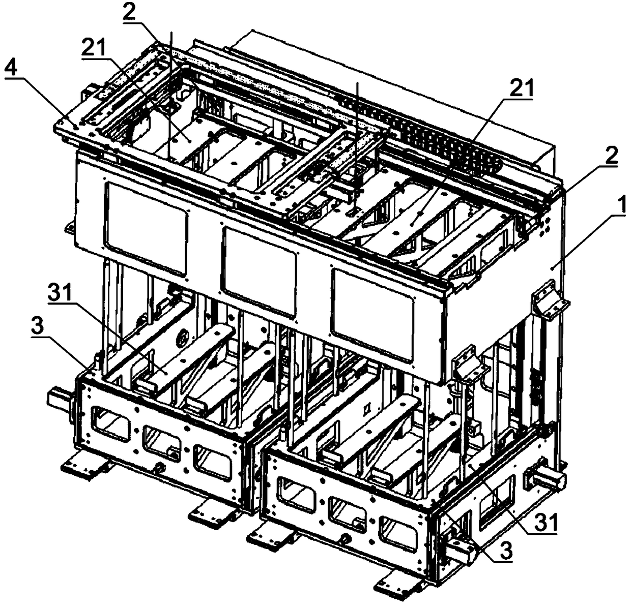
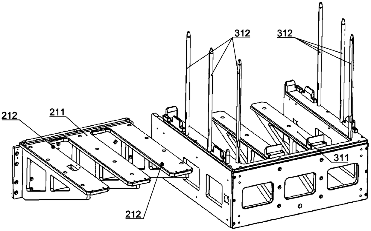
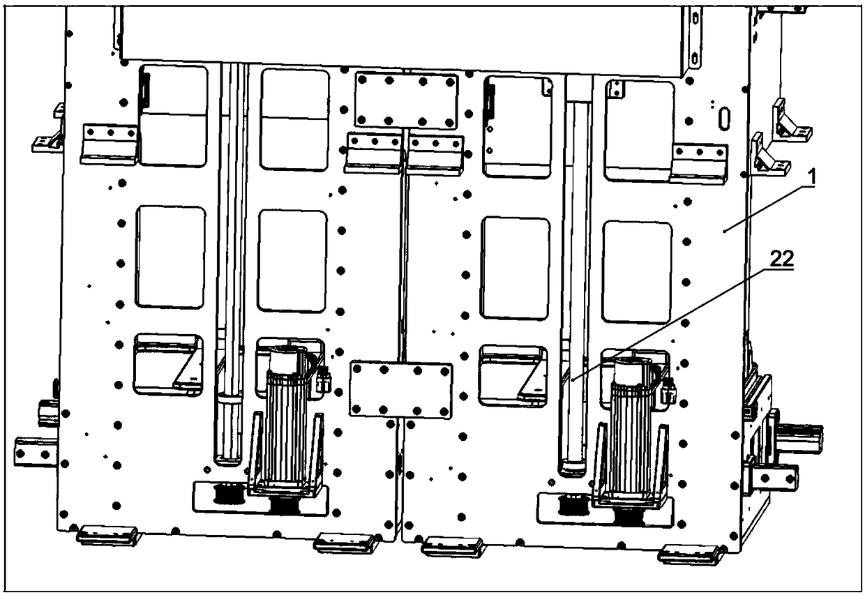
[0046] This embodiment provides a clip-type feeding mechanism, the structure of which is as follows: figure 1 Shown, comprise frame 1, have on the frame 1 the feeding area ( figure 1 middle left) and return area ( figure 1 Middle right side), the ends of the feeding area and the returning area have a transfer area connected to each other, and the other ends of the feeding area and the returning area respectively have a material transfer area for loading and unloading materials, wherein the transfer area includes the upper feeding area and unloading area. The feeding area on the left is the transfer area when the material tray with the workpiece is transported from the loading area, and the clamping device located on the upper part of the transfer area takes the workpiece away. A transfer mechanism 4 is provided in the transfer area, and the transfer mechanism 4 reciprocates on the transfer area for transferring the tray between the feeding area and the returning area. . A ...


PUM


Abstract

The invention provides a clip type feeding mechanism which comprises a rack and a transfer mechanism. The rack is provided with a feeding area and a material returning area which are used for carryingmaterial plates and arranged in parallel. The ends of the feeding area and the material returning area are provided with transferring areas which communicate with each other. The other end portions of the feeding area and the material returning area are provided with a feeding area used for material feeding and a discharging area used for material discharging. The transfer mechanism moves in thetransferring area and carries the material plates to the material returning area. The feeding area and/or the material returning area are/is provided with a lifting device and a horizontal moving device which are independent from each other. The lifting device is used for conveying the material plates among the transferring area, the feeding area and the discharging area through lifting motion; the horizontal moving device is used for inputting the material plates to or outputting the material plates from the feeding area and the discharging area through horizontal motion; and the lifting device penetrates the horizontal moving device in a lifting manner and transfers the material plates to the horizontal moving device. By means of the clip type feeding mechanism, material plate lifting, feeding and carrying work can be conducted while the material plates are loaded and unloaded.

Description

technical field [0001] The invention relates to the technical field of material handling devices, in particular to a clip-type feeding mechanism. Background technique [0002] In the automatic assembly and production process, it is necessary to batch load various parts. In the existing technology, due to the low degree of automation, some operations inevitably require manual assistance, and the number of parts on site is large and dense. Especially for some smaller parts, it is easy to cause problems such as high work intensity of on-site operators, large feeding errors, and low feeding efficiency. [0003] There is an existing automatic feeding mechanism for the tray, the two sides and the middle of the base and the top frame are provided with ball screws, and a tray ascending and descending mechanism is arranged between the ball screws; a servo motor is arranged below the tray ascending and descending mechanism; The outer side of the screw rod is also provided with a phot...

Claims


Application Information

Patent Timeline
Patent Type & Authority Applications(China)
IPC IPC(8): B65G47/06B65G37/02
CPCB65G37/02B65G47/06
Inventor 吴加富缪磊高冬青郑文坛郑俊杰冯小平
Owner SUZHOU RS TECH
Why Eureka
Try Eureka