Continuous and automatic steel wire rod pay-off rack

A technology for pay-off racks and wire rods, which is used in the transportation of filamentous materials, thin material handling, transportation and packaging, etc. It can solve the problems of easy-to-disrupt pay-off lines, abnormal wear on the surface of wire rods, and good wire rod stiffness and high stress. , to avoid equipment damage, improve product quality, and reduce maintenance costs

Pending Publication Date: 2018-12-21
河南巨力钢丝绳制造有限公司
View PDF15 Cites 4 Cited by
  • Summary
  • Abstract
  • Description
  • Claims
  • Application Information

AI Technical Summary

Problems solved by technology

[0002] Due to the material properties of the wire rope industry, there is a problem of heavy material transfer weight in the pretreatment production process. The existing wire rope wire rod is straightened and processed by the pay-off car and the wire drawing car platform. After the pay-off car is finished, It is necessary to manually control the driving and transfer it away from the pay-off car, and then transfer it to another pay-off car to pay off the wire. After the wire rod is paid out, it will be processed into a steel wire rope product during the transportation process. Due to the limitation of the packaging structure of the wire rod, it will be rolled. And there is a requirement for the direct

Method used


Image

  • Continuous and automatic steel wire rod pay-off rack
  • Continuous and automatic steel wire rod pay-off rack
  • Continuous and automatic steel wire rod pay-off rack

Examples


Embodiment 1

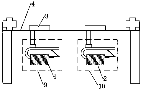
[0020] Such as Figure 1-Figure 3 As shown, a continuous automatic wire rod pay-off rack includes two parallel tracks 4, a bridge mounted on the parallel tracks 4 and perpendicular to the tracks, a pay-off area 10 and a preparation area 9, a release area 10 and a preparation area 9 are equipped with electromagnetic sucker cranes 3 that move horizontally along the bridge frame. The first pay-off car 2 is provided in the pay-off area 10, and the first pay-off car 2 moves along the track 4 through the electromagnetic sucker crane 3. The preparation area 9 is equipped with a first The second pay-off car 1, and the second pay-off car 1 moves along the track 4 through the electromagnetic sucker crane 3, and the electromagnetic sucker crane 3 is controlled by a PLC controller;

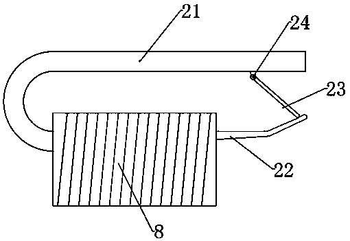
[0021] The first and the second pay-off car are all provided with L-shaped disorderly wire protection frame 23, and the disorderly wire protection frame 23 is provided with a disorderly wire protection sensor...


PUM


Abstract

The invention belongs to the technical field of steel wire rope pay-off devices, and in particular, relates to a continuous and automatic steel wire rod pay-off rack. The continuous and automatic steel wire rod pay-off rack comprises a pay-off area and a preparation area, so that steel wire rods are continuously and automatically released; when a first pay-off car in the pay-off area is located ina pay-off working state, the tail end of a steel wire rod of the first pay-off car is welded with the head end of a steel wire rod of a second pay-off car in the preparation area to guarantee the steel wire rod pay-off continuity; when the wire releasing of the first pay-off car is finished, an electromagnetic disc crane transfers the first pay-off car to a steel wire rod warehouse for steel wirerod penetration; the second pay-off car in the preparation area enters the pay-off area for wire releasing; the first pay-off car with the steel wire rods is placed in the position of the first pay-off car in an original preparation area by a crane; the operation is repeated, so that the steel wire rod pay-off consistency and continuity are guaranteed, the production efficiency is improved, the staff operation is convenient and safe, and the manpower consumption is reduced; and in addition, in the pay-off straightening process of the steel wire rods, a protection mechanism is provided for instantly detecting the wire quality and the pay-off conditions, so that the steel wire rope product quality is improved.

Description

technical field [0001] The invention belongs to the technical field of wire rope pay-off devices, and in particular relates to a continuous automatic wire rod pay-off frame. Background technique [0002] Due to the material properties of the wire rope industry, there is a problem of heavy material transfer weight in the pretreatment production process. The existing wire rope wire rod is straightened and processed by the pay-off car and the wire drawing car platform. After the pay-off car is finished, It is necessary to manually control the driving and transfer it away from the pay-off car, and then transfer it to another pay-off car to pay off the wire. After the wire rod is paid out, it will be processed into a steel wire rope product during the transportation process. Due to the limitation of the packaging structure of the wire rod, it will be rolled. And there is a requirement for the direction of the wire when it is paid off, and the rigidity of the wire rod itself is go...

Claims


Application Information

Patent Timeline
IPC IPC(8): B65H67/06B65H63/06B65H63/00
CPCB65H63/006B65H63/06B65H67/06B65H2701/30
Inventor 施聪夏利科汤庆辉
Owner 河南巨力钢丝绳制造有限公司
Why Eureka
Try Eureka