High quality printing and dyeing mechanism of textile fabric

A textile fabric, high-quality technology, applied in the direction of processing textile material equipment configuration, spray/jet textile material processing, etc., can solve the problems of adhered impurities, uneven dyeing, poor dyeing effect, etc., and achieves ingenious and reasonable structure and effect. Good, improve the effect of utilization

Active Publication Date: 2018-12-21
浙江盛邦化纤有限公司
View PDF6 Cites 2 Cited by
  • Summary
  • Abstract
  • Description
  • Claims
  • Application Information

AI Technical Summary

Problems solved by technology

[0005] The purpose of the present invention is to address the deficiencies of the prior art, to provide a high-quality printing and dyeing mechanism for textile fabrics, which grinds the dye liquor at the bottom by setting a filter assembly and a grinding assembly, and sprays the filtered dye liquor The components are sprayed to dye the dip-dyed fabric, thereby solving the problems of poor fabric dyeing effect, uneven dye, easy deposition of dye at the bottom, and impurities on the surface of the dip-dyed fabric

Method used


Image

  • High quality printing and dyeing mechanism of textile fabric
  • High quality printing and dyeing mechanism of textile fabric
  • High quality printing and dyeing mechanism of textile fabric

Examples


Embodiment 1

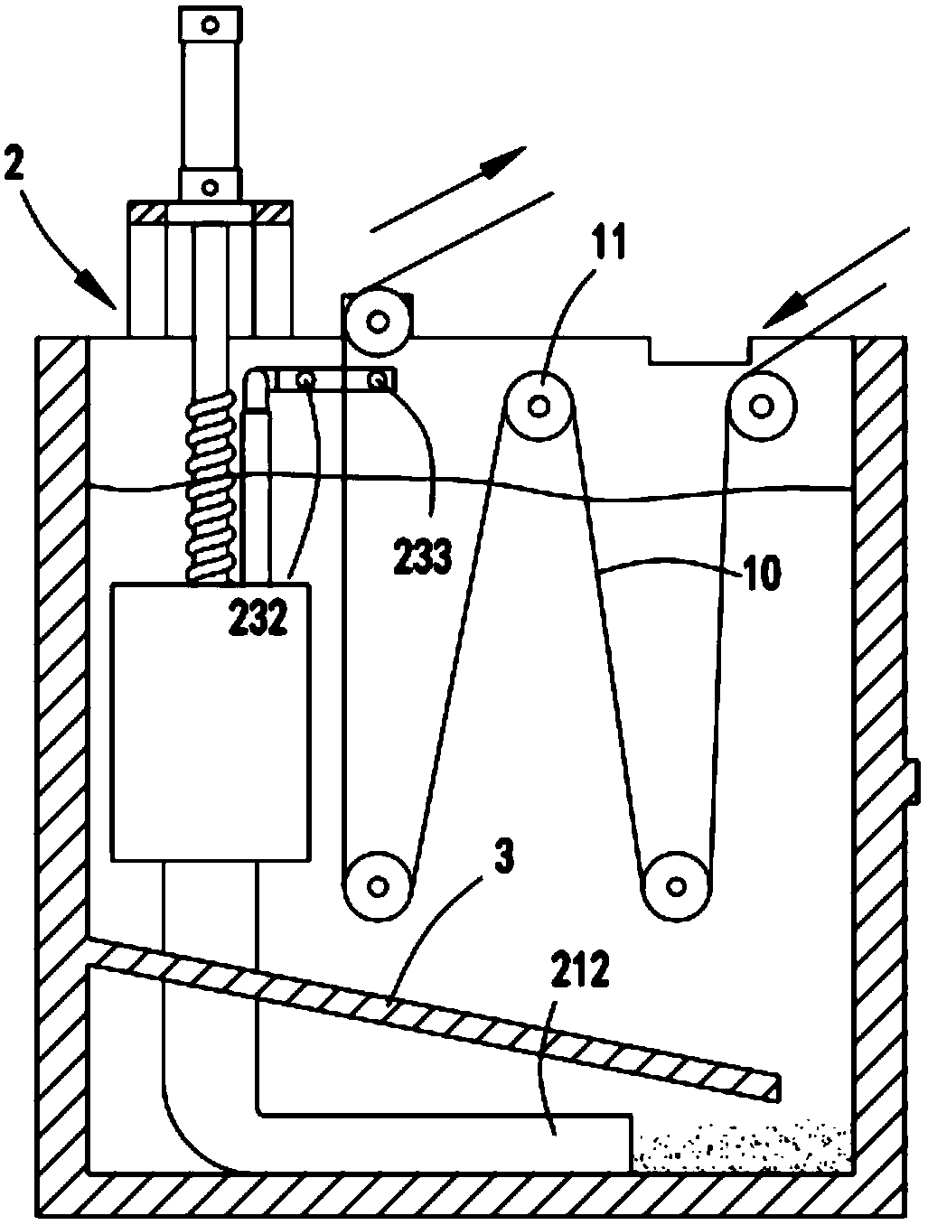
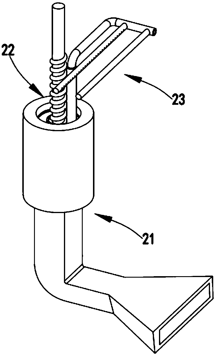
[0042] Such as Figure 1 to Figure 11 As shown, a high-quality textile fabric printing and dyeing mechanism includes a dye box 1, in which a spray dyeing mechanism 2 is provided, and the spray dyeing mechanism 2 includes a filter assembly 21 fixed on the inner wall of the dye box 1, and The grinding assembly 22 in the filter assembly 21 and the spray dye assembly 23 provided on the upper end of the filter assembly 21;

[0043] When the grinding assembly 22 moves upward, the filter assembly 21 draws the dye liquor from the bottom of the dye box 1. When the grinding assembly 22 moves downward, the dye liquor in the filter assembly 21 is squeezed and the dye liquor is filtered. The filtered dye liquor Under pressure, the two sides of the fabric 10 are sprayed and dyed by the spray dyeing assembly 23. After the dyeing solution is squeezed and sprayed, the grinding assembly 22 continues to move downward to prevent the coarse particles of dye remaining in the filter assembly 21. Grind...

Embodiment 2

[0059] Such as figure 1 As shown, the components that are the same as or corresponding to those in the first embodiment use the reference numerals corresponding to those in the first embodiment. For the sake of simplicity, only the differences from the first embodiment are described below. The second embodiment is different from the first embodiment in that: further, a guide plate 3 is provided under the filter assembly 21, and the end of the guide plate 3 is inclined downward toward the entrance of the suction pipe 212.

[0060] In this embodiment, by setting the guide plate 3 at the bottom of the dye box 1, some of the deposited coarse-particle dye and impurities flow along the guide plate 3 to the port of the suction pipe 212, which improves the efficiency of coarse-particle dye collection and grinding.

[0061] The working process is as follows:

[0062] The lifting member 222 drives the lead screw 223 to move downward. At this time, the communicating groove c228 is located above...


PUM


Abstract

The invention relates to a high quality printing and dyeing mechanism of textile fabric, which comprises a dye box. A spray dyeing mechanism is arranged in the dye box, wherein the spray dyeing mechanism comprises a filter assembly, a grinding assembly arranged in the filter assembly and a spray dyeing assembly arranged on the filter assembly; the grinding assembly moves upward so that the filterassembly extracts the dye solution at the bottom of the dye box, and moves downward so that the filter assembly compresses the dye solution in the filter assembly and filters the dye solution. The filtered dye solution sprays out through the spray dyeing assembly. After the solution is sprayed and dyed, the grinding assembly continues to move downwards to grind the coarse particle dye remaining inthe filter assembly. A plurality of cloth guide rollers are arranged in the dye box, and the fabric is transmitted from the dye box from the bottom to the top under the guidance of the cloth guide rollers. The spray dyeing assembly comprises a duct a and a spray dyeing tube a and a spray dyeing tube b. The spray dyeing tube a and the spray dyeing tube b are respectively arranged on both sides ofthe fabric; the high quality printing and dyeing mechanism of textile fabric solves the problems of poor dyeing effect, uneven dyes, easy deposition of dyes at the bottom and staining impurities on the surface of fabric after dyeing.

Description

Technical field [0001] The invention relates to the technical field of textile printing and dyeing equipment, in particular to a high-quality printing and dyeing mechanism for textile fabrics. Background technique [0002] Textile printing and dyeing is also called dyeing and finishing, which is a kind of processing method. It is also a general term for pretreatment, dyeing, printing, finishing, washing and so on. The existing dyeing methods include dip dyeing and spray dyeing. Its solubility is general, and it is easy to deposit after a long time. The dye at the bottom is heavy, and the dye on the surface is light, which affects the dyeing effect. [0003] A Chinese utility model patent with the authorized announcement number CN. discloses a textile printing and dyeing device, and specifically discloses that there are two printing and dyeing boxes on the support frame, and the driving part is used to control the drive rod to telescopically control the up and down movement of the s...

Claims


Application Information

Patent Timeline
Patent Type & Authority Applications(China)
IPC IPC(8): D06B1/02D06B23/20
CPCD06B1/02D06B23/20
Inventor 张辰罗冬英
Owner 浙江盛邦化纤有限公司
Why Eureka
Try Eureka