Construction method of cast-in-place box girder with variable curvature based on adjustable formwork

A box girder construction and shaping technology, used in bridges, bridge construction, erection/assembly of bridges, etc., can solve the problems affecting the spatial alignment of bridge structures and the quality of pouring construction, the difficulty of ensuring the quality of concrete maintenance, and the poor production effect of steel cages, etc. problems, to achieve the effect of fast moisturizing and maintenance, convenient assembly, and reducing the requirements for personnel

Active Publication Date: 2018-12-21
SICHUAN RAILWAY CONSTR CO LTD
View PDF7 Cites 9 Cited by
  • Summary
  • Abstract
  • Description
  • Claims
  • Application Information

AI Technical Summary

Problems solved by technology

[0003] At present, in the construction of variable-curvature cast-in-place box girders, pads are often used to adjust the transverse slope, the formwork line is adjusted by changing the formwork structure, and sprinklers are used to sprinkle water for concrete maintenance. Although these technologies have achieved certain engineering results under suitable working conditions, but for The cast-in-place box girder with complex spatial alignment and large cross-sectional size is prone to problems such as low formwork positioning accuracy, poor reinforcement cage production effect, and difficult to guarantee the quality of concrete maintenance, which seriously affects the spatial alignment of the bridge structure and the quality of pouring construction

Method used


Image

  • Construction method of cast-in-place box girder with variable curvature based on adjustable formwork
  • Construction method of cast-in-place box girder with variable curvature based on adjustable formwork
  • Construction method of cast-in-place box girder with variable curvature based on adjustable formwork

Examples


Embodiment Construction

[0034] Construction technical requirements for construction platform layout, on-site welding construction technical requirements, concrete mix ratio design and pouring construction technical requirements, formwork design and construction technical requirements, built-in sliding water spray device production and water spray construction technical requirements, etc., are not included in this embodiment. The details will be described again, and the embodiments of the methods involved in the present invention will be focused on.

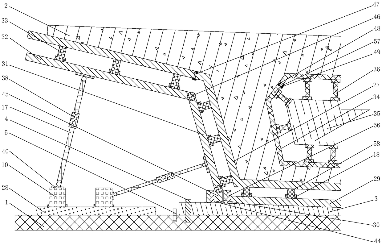
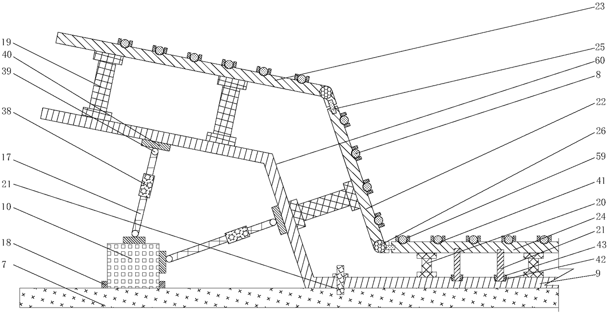
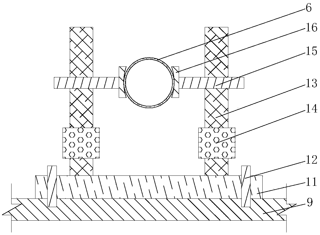
[0035] figure 1 It is a schematic diagram of the pouring structure of the cast-in-place box girder based on the variable curvature of the adjustable formwork of the present invention; figure 2 It is a schematic cross-sectional view of the steel bar positioning tire frame structure of the present invention; image 3 It is a schematic cross-sectional view of the pre-embedded pipe fitting positioning structure of the present invention; Figure 4 It is a ...


PUM


Abstract

The invention relates to A method for construct cast-in-situ box girder with variable curvature base on adjustable formwork which features that a super-high regulator is used to control that transverse super-height of cast-in-situ box girder. Arc-shaped clip is arranged at the end of the positioning cross bar for positioning the embedded pipe. Reinforcement cage of box girder is prepared by reinforcement positioning jig; Setting a shelf limit guide groove on the outer side of the shelf bottom plate; A lateral wall adjust beam is arranged between that out mold and the side member of the bow frame and the top member of the bow frame, and a bottom adjusting beam is arranged between the side mold and the bottom plate of the shelf; An inner mold supporting beam is arranged between the inner mold supporting body and the inner mold, and the inner mold supporting beam and the inner mold are connected by bolts; The joint bolt is located on the inner die. The bottom adjusting beam is positionedbetween the inner mold and the shelf bottom plate; The inner side of the cast-in-place box girder is maintained by the built-in sliding water spraying device. The invention can effectively improve thequality of the space alignment positioning of the cast-in-place box girder, the binding of the reinforcing bar cage and the on-site moisture preservation and curing, and improve the on-site construction efficiency.

Description

technical field [0001] The invention relates to a construction method of a cast-in-place box girder, in particular to a cast-in-place box girder based on an adjustable and stereotyped formwork with variable curvature, which has the advantages of convenient formwork assembly, accurate space alignment control, high preparation accuracy of box girder reinforcement cages, and good on-site maintenance quality. The construction method belongs to the field of bridge engineering and is suitable for construction projects of variable curvature cast-in-place box girders. Background technique [0002] With the continuous improvement of the level of bridge construction, the structural form and spatial alignment of bridges are becoming more and more complex. During the construction of the curved section of the bridge, especially during the construction of the transition section and the circular curved section, problems such as the support of the curved formwork, the adjustment of the tran...

Claims


Application Information

Patent Timeline
Patent Type & Authority Applications(China)
IPC IPC(8): E01D21/00E01D2/04
CPCE01D2/04E01D21/00
Inventor 王新泉
Owner SICHUAN RAILWAY CONSTR CO LTD
Why Eureka
Try Eureka