
S-shape throwing and withdrawing control method of hydroelectric unit servomotor locking device

A technology of hydroelectric unit and locking device, applied in safety devices, hydroelectric power generation, machines/engines, etc., can solve the problems of overtime of single-step process of starting and stopping, failure of automatic starting and stopping, etc.

Active Publication Date: 2020-05-26
CHINA YANGTZE POWER
View PDF7 Cites 0 Cited by
  • Summary
  • Abstract
  • Description
  • Claims
  • Application Information

AI Technical Summary

Problems solved by technology

However, the closed-loop locking control method still has a large impact at the starting point, and the time spent in the process of switching on and off is more than 6 times that of the open-loop mode, which will cause the single-step process of starting and stopping to time out, resulting in failure of automatic starting and stopping

Method used


Image

  • S-shape throwing and withdrawing control method of hydroelectric unit servomotor locking device
  • S-shape throwing and withdrawing control method of hydroelectric unit servomotor locking device
  • S-shape throwing and withdrawing control method of hydroelectric unit servomotor locking device

Examples


Embodiment Construction

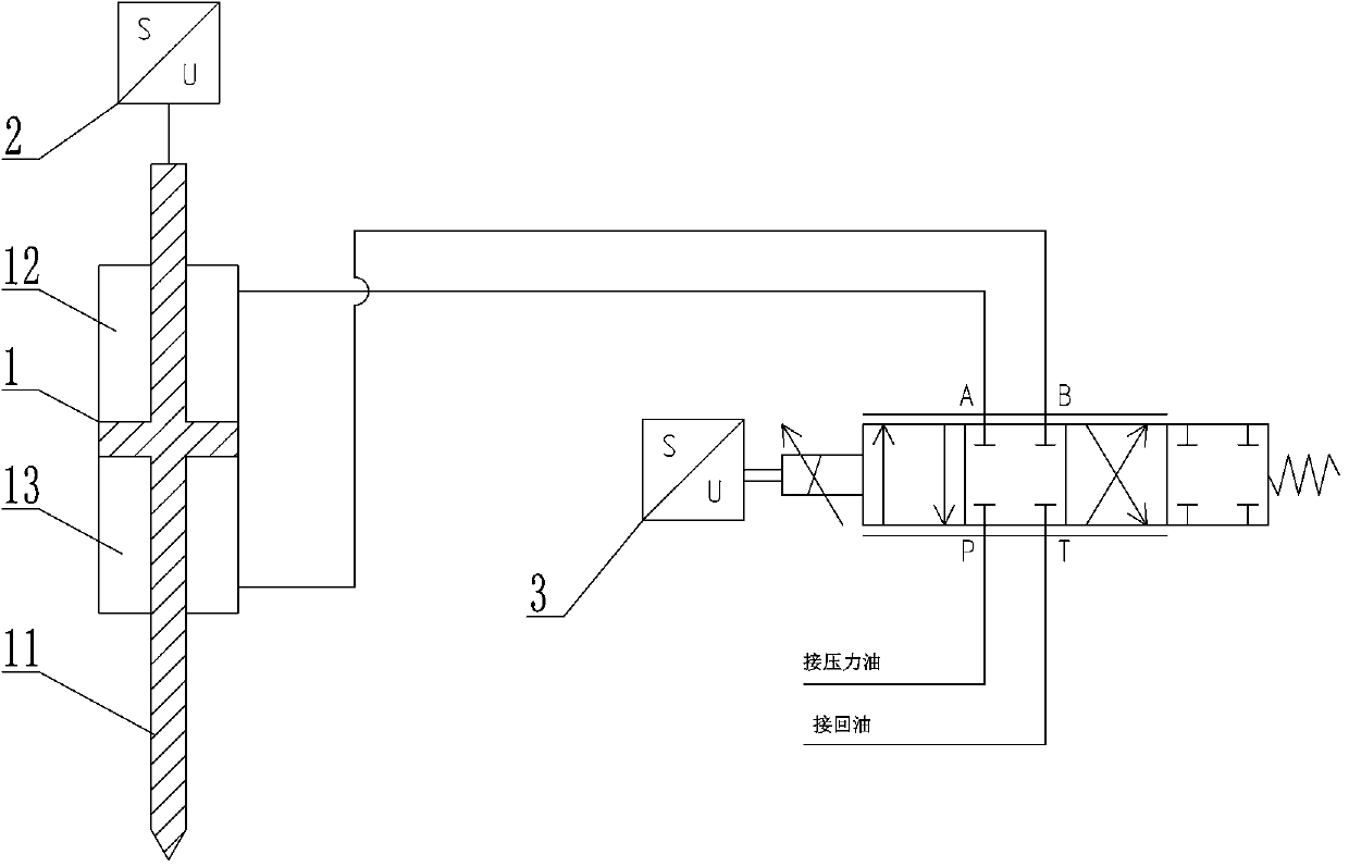
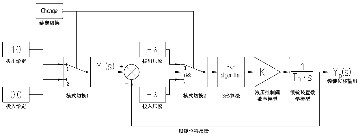
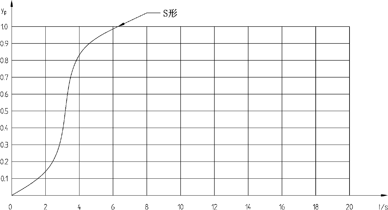
[0024] like Figure 1~Figure 6 Among them, an S-shaped throwing and withdrawing control method of a hydroelectric unit servomotor locking device, which includes a locking servomotor 1, a displacement sensor 2 located at the rear of a locking lever 11, and a hydraulic control valve connected to the input chamber 12 and the withdrawal chamber 13 respectively 3. When the locking rod 11 of the locking servomotor 1 is cast and withdrawn, the starting position moves slowly and accelerates, the middle position moves quickly, and the end position moves slowly and decelerates. The curve of the displacement of the locking rod 11 versus time is "S" shape. Realize that the spindle locking device has good cushioning performance whether it is at the starting position or the end position of the throwing and retreating control, and also takes into account the rapidity of throwing and retreating control, and the position of the spindle locking device will not be changed by mistake when the con...


PUM


Abstract

The invention provides an S-shaped feeding and withdrawing control method of a locking device for a servomotor of a hydroelectric generating set. The locking device comprises a locking servomotor, a displacement sensor positioned at the rear part of a locking bar, and hydraulic control valves connected with a feeding cavity and a withdrawing cavity separately; when the locking bar of the locking servomotor is fed or withdrawn, the locking bar does accelerated movement slowly at the start point position, rapidly moves at the middle position, and does decelerated movement when being close to thefinal point position; and the curve between the displacement of the locking bar and the time is S-shaped. Through the adoption of the S-shaped feeding and withdrawing control method, the problem thatthe impact force is too large when guide vanes of an original hydroelectric generating set are controlled to be locked is solved, the structure is simple, the curve between the displacement of the locking device and the time is S-shaped, the fact that the locking device has high buffer performance in the start point position or the final point position of feeding and withdrawing control is realized, realizes fast feeding and withdrawing control, and avoids mistaken change of the position of the locking device caused when a controller is powered on.

Description

technical field [0001] The invention belongs to the technical field of throwing and withdrawing control of guide vanes of a hydroelectric unit, and relates to an S-shaped throwing and withdrawing control method of a servomotor locking device of a hydroelectric unit. Background technique [0002] The guide vane servomotors of hydro-generator sets are all equipped with locking devices. After the unit is shut down and the guide vanes are fully closed, the device needs to be put into use to prevent the guide vanes from opening due to misoperation of the servomotor, thus ensuring the safety of hydropower plant equipment and personnel. safety; before the governor is turned on, the locking device needs to be pulled out so that the guide vanes can be opened smoothly. [0003] For the locked throwing and withdrawing control and position detection, the traditional control method adopts pure open-loop control. This method uses a two-position four-way reversing solenoid valve to contro...

Claims


Application Information

Patent Timeline
Patent Type & Authority Patents(China)
IPC IPC(8): F03B15/00F03B3/18
CPCF03B3/183F03B15/00Y02E10/20
Inventor 田源泉张辉李辉汪林胡洪军徐龙
Owner CHINA YANGTZE POWER
Learn More