
A vehicle wheel-side composite braking device integrating permanent magnet braking and friction braking

A friction braking and compound braking technology, applied in the components of brakes, brake discs, brake types, etc., can solve the problems of large air gap between magnetic lines of force, small braking torque, low magnetic efficiency, etc. Increase braking torque and reduce wear

Active Publication Date: 2020-01-24
合肥九州龙腾科技成果转化有限公司
View PDF15 Cites 11 Cited by
  • Summary
  • Abstract
  • Description
  • Claims
  • Application Information

AI Technical Summary

Problems solved by technology

[0005] The purpose of the present invention is to solve the problem of the low integration of existing permanent magnet braking and friction braking, the small braking torque that the permanent magnet braking device can provide, and the large air gap of the magnetic line of force when the permanent magnet braking works, which makes the magnetic The efficiency is low, and it is not suitable for high-quality integrated control with electronically controlled friction braking. Therefore, a vehicle wheel-side composite braking device integrating permanent magnet braking and friction braking is proposed.

Method used


Image

  • A vehicle wheel-side composite braking device integrating permanent magnet braking and friction braking
  • A vehicle wheel-side composite braking device integrating permanent magnet braking and friction braking
  • A vehicle wheel-side composite braking device integrating permanent magnet braking and friction braking

Examples


Embodiment Construction

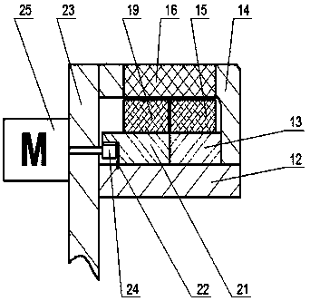
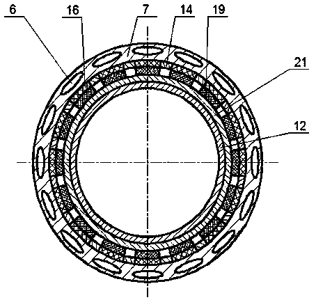
[0020] Such as figure 1 As shown, the vehicle wheel compound braking device integrating permanent magnet braking and friction braking according to the present invention includes: friction braking assembly, permanent magnetic braking assembly, integrated brake disc 7 and planetary gear mechanism, each part All can be independently installed on the wheel edge of each wheel.

[0021] Such as figure 1 , 2 As shown, the integrated brake disc 7 is an intermediate connecting body between the friction brake assembly and the permanent magnet brake assembly. The integrated brake disc 7 is cylindrical in shape, the left end of the cylindrical shape in the axial direction is open, the right end face is closed, and a central through hole 20 is opened in the middle of the right end face, and the coaxial fixed sleeve in the central through hole 20 has a rotating Axis 11. There are several closed sodium-filled cavities 6 evenly distributed along the circumference in the side wall of the i...


PUM


Abstract

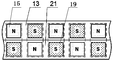
The invention discloses a vehicle wheel rim composite brake device integrating permanent magnet braking and friction braking, and belongs to the field of vehicle braking. A support base ring is coaxially sleeved with an integrated brake disc, the support base ring is coaxially and fixedly sleeved with a magnetic circuit guide frame, a plurality of magnetic conductive pole pieces are evenly embedded in the side wall of the magnetic circuit guide frame in the circumferential direction, the support base ring is sleeved with a movable magnet support through a bearing, the support base ring is fixedly sleeved with a fixed magnet support, a plurality of movable magnets are evenly and fixedly connected to the outer wall of the movable magnet support in the circumferential direction, a plurality of fixed magnets are evenly and fixedly connected to the outer wall of the fixed magnet support in the circumferential direction, the movable magnets and one fixed magnet are arranged left and right inthe axial direction, the fixed magnets and the movable magnets which are opposite in the axial direction at the initial position are opposite in magnetizing direction, the movable magnets are rotatedto enable each movable magnet and the corresponding fixed magnet opposite to the movable magnet in the axial direction to be the same in magnetizing direction during permanent magnet braking, brakingenergy is shared through non-contact permanent magnet braking, and friction braking abrasion is reduced.

Description

technical field [0001] The invention belongs to the technical field of vehicle braking, and in particular relates to a composite braking device integrating permanent magnet braking and friction braking. Background technique [0002] The braking system is one of the important components of the automobile chassis. The traditional braking system includes hydraulic and pneumatic braking systems, which have complex pipeline layout, rely on vacuum booster devices, slow braking response speed, and insufficient braking torque. Inadequacies such as active adjustment and difficulty in integrated control with other systems are not suitable for the development requirements of integrated control of automobiles, especially electric vehicle chassis. The electronically controlled braking system that appeared later realized the decoupling of the brake pedal mechanism and the brake actuator. There are mainly two types of electronic hydraulic braking system (EHB) and electromechanical braking ...

Claims


Application Information

Patent Timeline
Patent Type & Authority Patents(China)
IPC IPC(8): F16D65/12F16D65/18F16D65/847F16D123/00F16D121/20F16D121/24F16D125/40F16D129/06
CPCF16D65/125F16D65/127F16D65/128F16D65/18F16D65/847F16D2065/1304F16D2121/20F16D2121/24F16D2123/00F16D2125/40F16D2129/065
Inventor 何仁王奎洋何平
Owner 合肥九州龙腾科技成果转化有限公司
Learn More