
Pneumatic butterfly valve

A pneumatic butterfly valve and valve body technology, applied in the field of industrial valve actuators and pneumatic butterfly valves, can solve the problems of wasting energy, lax valve closing, affecting energy saving and environmental protection, etc. Effect

Pending Publication Date: 2018-12-21
上海宏芃流体科技有限公司
View PDF0 Cites 3 Cited by
  • Summary
  • Abstract
  • Description
  • Claims
  • Application Information

AI Technical Summary

Problems solved by technology

The opening and closing controller sets the opening and closing position of the valve to adjust the opening and closing of the valve. Due to the large position error, the valve is not closed tightly, resulting in fluid leakage and wasting energy. The quality cannot be guaranteed, which seriously affects energy conservation and environmental protection.

Method used


Image

  • Pneumatic butterfly valve
  • Pneumatic butterfly valve

Examples


Embodiment Construction

[0012] In order to make the present invention more comprehensible, preferred embodiments are described in detail below with accompanying drawings.

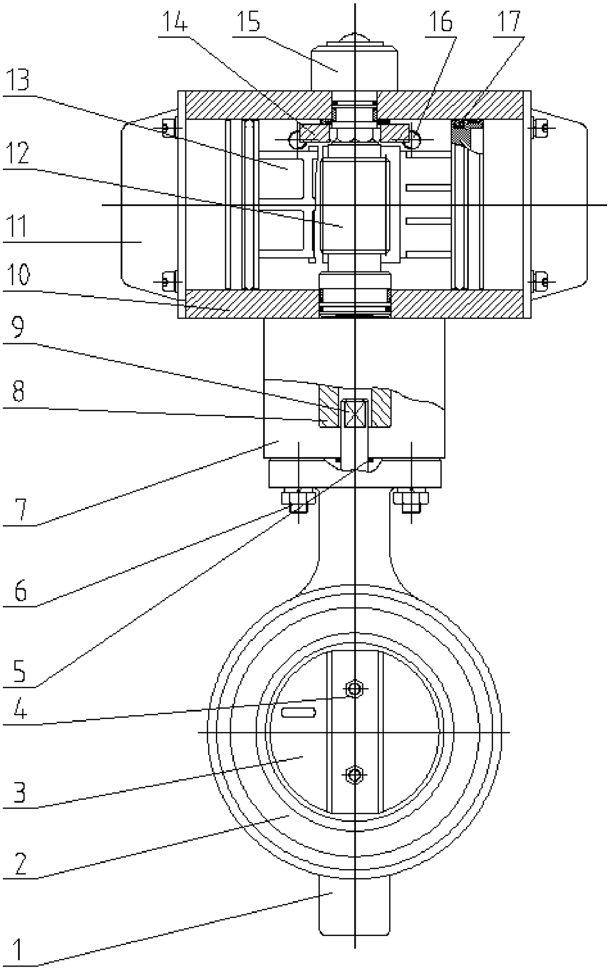
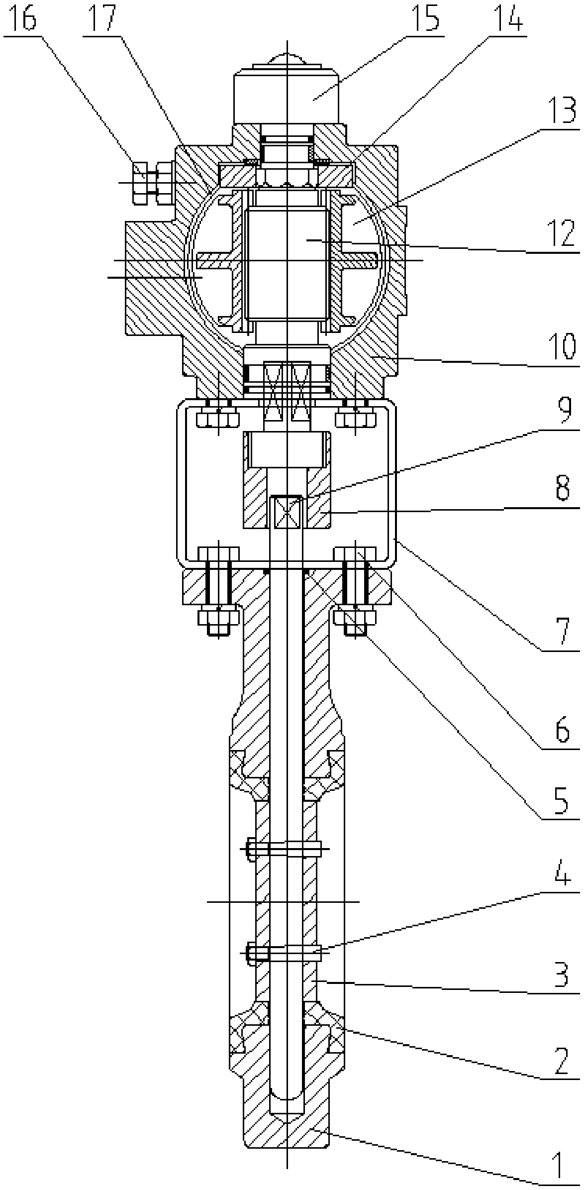
[0013] The invention is mainly composed of rotary valve sealing parts, valve body parts, cylinder driving actuators and other parts. The rotary valve is driven by the cylinder to drive the actuator to rotate and open and close, so as to open the fluid and block the flow of the fluid.

[0014] to combine figure 1 and figure 2 , the present invention is mainly composed of valve body 1, sealing ring 2, valve 3, valve stem 9, bracket 7, cylinder actuator and the like. The cylinder actuator is mainly composed of a cylinder block 10, an end cover 11, a rack piston 13, a gear output shaft 12, an indicator 15, an adjusting screw 16, a piston sealing ring 17, and the like.

[0015] The valve 3 is installed on the valve stem 9 through the positioning pin 4, and the two ends of the valve stem 9 are placed in the positioning shaft hole of...


PUM


Abstract

The invention provides a pneumatic butterfly valve which comprises a valve body, wherein a valve rod is arranged in the valve body in a penetrating manner; the upper end of the valve rod is exposed tothe external part of the valve body; a valve is arranged in the middle of the valve rod; the pneumatic butterfly valve is characterized in that the upper end of the valve rod is positioned in a bracket; the valve body and a cylinder are connected and fixed with the bracket; the upper end of the valve body is connected with a connecting block in the bracket; a gear output shaft is arranged in thecylinder and is connected with the connecting block; two rack pistons are symmetrically arranged on the two sides of the gear output shaft; the gear on the gear output shaft is meshed with the racks of the two rack pistons; the two rack pistons do straight reciprocating motion through air source pressure; and the rack pistons drive the gear output shaft to rotate during the moving process. The pneumatic butterfly valve adopts the air as the power source to control the butterfly valve to be automatically closed and opened, so that the error is reduced. In addition, the air has the advantages ofbeing convenient to collect and free of pollution, is suitable for being used in the anti-explosion and flame-proof field and has wide application prospect in the service field.

Description

technical field [0001] The invention relates to a pneumatic butterfly valve, which is an actuator of industrial valves and belongs to the technical field of industrial valves. Background technique [0002] The traditional butterfly valve is composed of a valve sealing part, a valve body, and an opening and closing control part. It is a manual device. The valve sealing part relies on the opening and closing control part to operate to achieve the purpose of opening and blocking fluid flow. The opening and closing controller sets the valve opening and closing gears to adjust the valve opening size. Due to the large gear position error, the valve is not closed tightly, resulting in fluid leakage, wasting energy, and quality cannot be guaranteed, which seriously affects energy conservation and environmental protection. Contents of the invention [0003] The purpose of the present invention is to provide a butterfly valve with good pressure resistance and sealing performance. ...

Claims


Application Information

Patent Timeline
Patent Type & Authority Applications(China)
IPC IPC(8): F16K31/122F16K1/22F16K41/06
CPCF16K1/221F16K1/2268F16K31/1225
Inventor 江明方
Owner 上海宏芃流体科技有限公司
Learn More