[0025] Embodiments of the present invention will be described in further detail below in conjunction with the accompanying drawings.
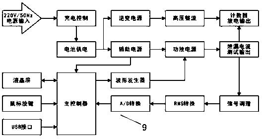
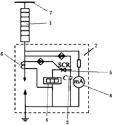
[0026] The non-residual-voltage large-flow arrester monitor detection device for UHV engineering of the present invention includes a lightning arrester 1, the lightning arrester 1 is grounded through a conductive wire, and the middle part of the conductive wire is disconnected. When lightning strikes the lightning arrester 1, the voltage can break through the middle of the conductive wire The open circuit of the electric wire is connected, and it is characterized in that: the monitor device also includes a lightning arrester monitor 2, and the lightning arrester monitor 2 is provided with a power supply, and the power supply is connected to a capacitor 3 through a rectification circuit to charge the capacitor 3, and the capacitor 3 and a capacitor 3 are charged. The counter 4 is connected in series, the circuit between the capacitor 3 and the counter 4 is connected with a thyristor 5, the gate of the thyristor 5 is connected to the conductive wire through the induction coil 6, and the anode and the cathode of the thyristor 5 are respectively connected to the capacitor 3 and the counter 4, when the conductive wire has When the current passes, the induction coil 6 senses the current, energizes the gate of the thyristor 5, triggers the action of the thyristor 5, and discharges the capacitor 3 to the counter 4, so that the counter 4 operates.
[0027] In the embodiment, the power source is a 1000KV busbar 7 .
[0028] In the embodiment, the 1000KV bus 7 can be disconnected from the lightning arrester 1 at the same time. When testing the function of the lightning arrester 1, the 1000KV bus 7 is used to input current to the lightning arrester 1 to simulate a lightning strike.
[0029] In the embodiment, the monitor device also includes a lightning protection test device 9, a power supply battery and a main controller are installed in the lightning protection test device 9, and the voltage of the power supply battery is divided into two paths, which are respectively supplied to the inverter power module and the auxiliary power module; After the module is connected to the high-voltage module, it is connected to the capacitor 3 to supply power to the capacitor 3. The main controller controls the output voltage of the capacitor 3 to test the discharge count. The auxiliary power supply is connected to a power amplifier power supply. After the module and the A/D conversion module, it is connected with the main controller.
[0030] In an embodiment, the main controller is a single-chip microcomputer.
[0031] In the embodiment, the power supply battery is a 12V/500mAH rechargeable lithium battery, and the battery life is 2-3 days.
[0032] In the embodiment, the panel of the lightning protection testing device 9 is provided with a mouse interface, a USB interface, a discharge test socket, a leakage current test socket and a power switch.
[0033] In the embodiment, a display screen is arranged on the panel of the lightning protection test device 9 .
[0034] In an embodiment, the display screen is a liquid crystal display screen.
[0035] The lightning protection test device 9 of the present invention is mainly composed of two parts, the upper part is power generation and output control, the lower part is the main controller and its peripherals, the structure is as follows figure 2 Shown:
[0036] The performance and characteristics of the device are:
[0037] 1) Built-in 12V/500mAH rechargeable lithium battery, the battery life can reach 2-3 days;
[0038] 2) The battery voltage is divided into two circuits, which are respectively supplied to the inverter power module and the auxiliary power module;
[0039] 3) After the inverter power supply is rectified and filtered by high voltage, the discharge voltage is stored at both ends of the internal large-capacity capacitor, and the output voltage is controlled by the relay to test the discharge count;
[0040] 4) The leakage current test output is the control signal output by the main controller, and the 50Hz sine wave signal is generated by the DDS waveform generator chip, and then output to the power amplifier power module, which is output after isolation and boosting by the transformer;
[0041] 5) The leakage current is converted into a true RMS DC signal by channel signal conversion, and read and displayed by the main controller after A/D conversion.
[0042] panel design as image 3 shown, including the following parts:
[0043] 1) Discharge test terminal
[0044] It includes two output terminals, red and black, and the output indicator light is in the middle. In the discharge test mode, this terminal outputs the voltage stored at both ends of the internal capacitor to make the discharge counter count.
[0045] 2) Leakage current test terminal
[0046] It includes two output terminals, red and black, and the output indicator light is in the middle. In the leakage current meter calibration mode, the adjustable AC current is output from this terminal.
[0047] 3) Ground terminal
[0048] The ground terminal of the instrument is connected to the panel and the shell to ensure safe operation.
[0049] 4) Power input
[0050]Externally connected to 220V AC mains, the charging indicator light is on, and the internal lithium battery is charged.
[0051] 5) Power switch
[0052] Controls the instrument's power on and off.
[0053] 6) Display screen
[0054] Full Chinese menu display, various settings, mode selection and other functional operations.
[0055] 7) Mouse
[0056] One-button shuttle button mode, three operation modes: left rotation, right rotation and middle confirmation button.
[0057] The main controller of the present invention is selected as the STM32F103VBT6 single-chip microcomputer, and the sine wave fundamental wave of the leakage current is generated by the DDS waveform generator AD9833. After the leakage current signal is amplified and filtered by the op amp OP07 circuit, it is sent to the true effective value converter LTC1966, converted into a DC voltage, and then output to the analog/digital converter of AD7705, converted into a digital signal, and finally sent to the main controller for calculation and processing. The high-voltage discharge output part is composed of an inverter power supply and a PWM controller composed of SG3525, which converts 12V DC voltage into 1000V AC voltage, and then rectifies and filters it, and stores it at both ends of a large-capacity capacitor, and outputs it through a relay.
[0058] The above are only preferred implementations of the present invention, and the protection scope of the present invention is not limited to the above-mentioned embodiments, and all technical solutions under the idea of the present invention belong to the protection scope of the present invention. It should be pointed out that for those skilled in the art, some improvements and modifications without departing from the principle of the present invention should be regarded as the protection scope of the present invention.