Terminal device

A technology of terminal equipment and metal frame, which is applied in the field of communication and can solve the problems of large size of terminal equipment

Active Publication Date: 2018-12-21
VIVO MOBILE COMM CO LTD
View PDF6 Cites 29 Cited by
  • Summary
  • Abstract
  • Description
  • Claims
  • Application Information

AI Technical Summary

Problems solved by technology

[0003] An embodiment of the present invention provides a terminal device to solve the problem that the terminal device needs to pr

Method used


Image

  • Terminal device
  • Terminal device
  • Terminal device

Examples


Embodiment Construction

[0015] The following will clearly and completely describe the technical solutions in the embodiments of the present invention with reference to the accompanying drawings in the embodiments of the present invention. Obviously, the described embodiments are some of the embodiments of the present invention, but not all of them. Based on the embodiments of the present invention, all other embodiments obtained by persons of ordinary skill in the art without creative efforts fall within the protection scope of the present invention.

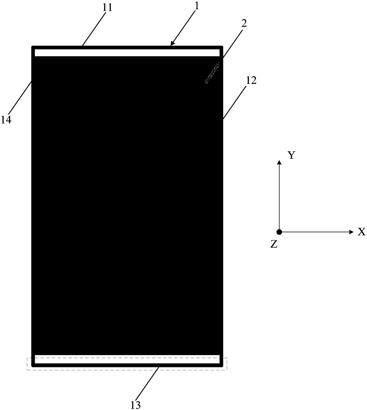
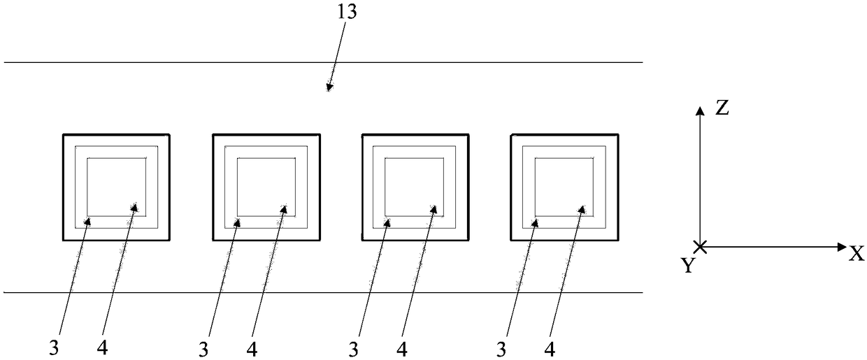
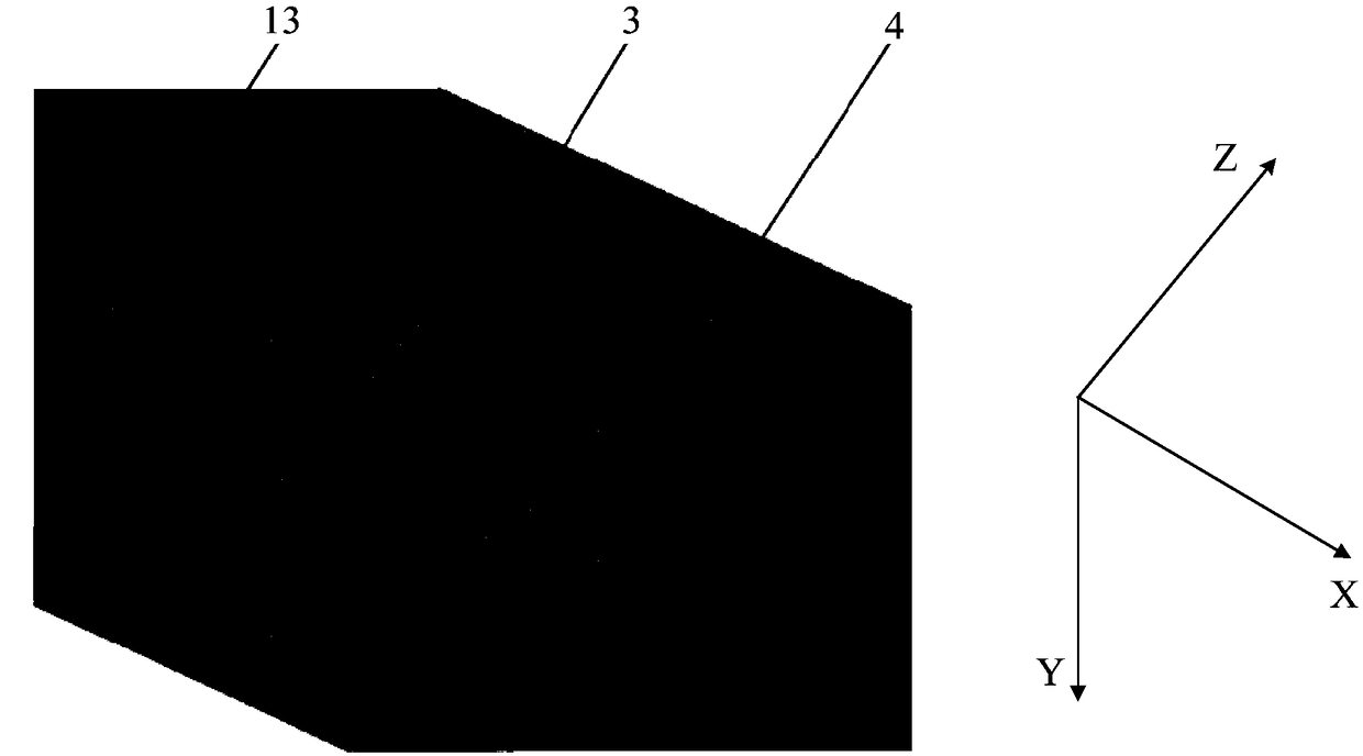
[0016] see figure 1 , figure 1 is a schematic structural diagram of a terminal device provided by an embodiment of the present invention, such as figure 1 As shown, it includes a feed source, a metal frame 1, a coupling sheet and a radiation sheet; the outer surface of the metal frame 1 is provided with at least two grooves, and each of the grooves is provided with two first through holes, and Each of the grooves is provided with a radiation sheet an...


PUM


Abstract

The invention provides a terminal device, which comprises a feed source, a metal frame, a coupling sheet and a radiation sheet. At least two grooves are arranged on the outer side of the metal frame,each groove is provided with two first through holes, and each groove is provided with a radiation plate and a coupling plate, and the metal frame is grounded; The coupling piece in each groove is arranged between the radiation piece and the bottom of the groove, and two second through holes are arranged on the coupling piece. Two antenna feeding points are arranged on each radiating plate, the feed source is connected to an antenna feeding point through a first through hole and a second through hole, and the antenna feeding points in each groove, the first through hole and the second throughhole correspond one by one; The metal frame, the coupling piece and the radiating piece are not in contact with each other and filled with non-conductive material. The area of radiating piece is smaller than that of coupling piece. Thus, the at least two grooves, the coupling plate, the radiating plate, and the feed correspond to the millimeter wave array antenna of the terminal device, thereby reducing the volume of the terminal device.

Description

technical field [0001] The present invention relates to the technical field of communications, and in particular to a terminal device. Background technique [0002] With the rapid development of communication technology, multi-antenna communication has become the mainstream and future development trend of terminal equipment, and in the process, millimeter wave antennas are gradually introduced into terminal equipment. In the prior art, the millimeter wave antenna is generally in the form of an independent antenna module, so it is necessary to provide an accommodating space for the independent antenna module in the terminal device. In this way, the size of the entire terminal device is relatively large, resulting in relatively low overall competitiveness of the terminal device. Contents of the invention [0003] An embodiment of the present invention provides a terminal device, so as to solve the problem that an accommodation space for a millimeter wave antenna needs to be...

Claims


Application Information

Patent Timeline
IPC IPC(8): H01Q1/22H01Q1/36H01Q1/44H01Q1/50H01Q21/00
CPCH01Q1/22H01Q1/36H01Q1/44H01Q1/50H01Q21/00H01Q9/045H01Q9/0414H01Q1/523H01Q1/243H01Q21/08H01Q9/0435H01Q5/40H01Q21/0031H01Q21/065
Inventor 黄奂衢王义金简宪静
Owner VIVO MOBILE COMM CO LTD
Why Eureka
Try Eureka