Supercharge Your Innovation With Domain-Expert AI Agents!

A magnetic steel separation device and a separation method for a rotor of a permanent magnet motor

A permanent magnet motor and separation device technology, which is applied in the direction of electromechanical devices, manufacturing motor generators, electrical components, etc., can solve problems such as increased labor burden, increased cost, and component damage, so as to reduce labor burden, avoid damage, The effect of reducing maintenance costs

Pending Publication Date: 2018-12-21
徐州给力磁业有限公司
View PDF0 Cites 0 Cited by
  • Summary
  • Abstract
  • Description
  • Claims
  • Application Information

AI Technical Summary

Problems solved by technology

However, in the later maintenance, once the permanent magnet motor rotor 1 is damaged and needs to be repaired, the new motor rotor can only be replaced as a whole. The assembly is too firm and difficult to be separated, and the overall replacement increases the cost; if violent disassembly is used, on the one hand, the labor burden is increased, and on the other hand, it is easy to damage the components

Method used


Image

  • A magnetic steel separation device and a separation method for a rotor of a permanent magnet motor
  • A magnetic steel separation device and a separation method for a rotor of a permanent magnet motor
  • A magnetic steel separation device and a separation method for a rotor of a permanent magnet motor

Examples


Embodiment Construction

[0021] The present invention will be described in further detail below in conjunction with the accompanying drawings.

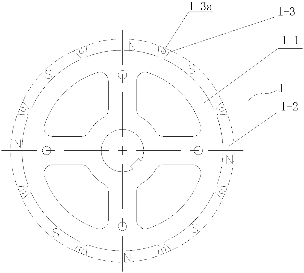
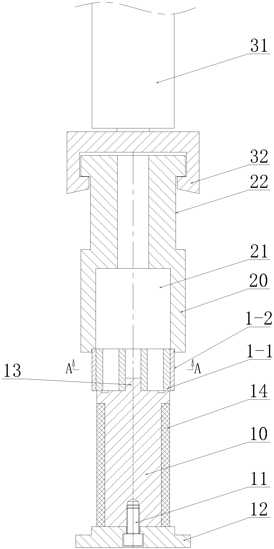
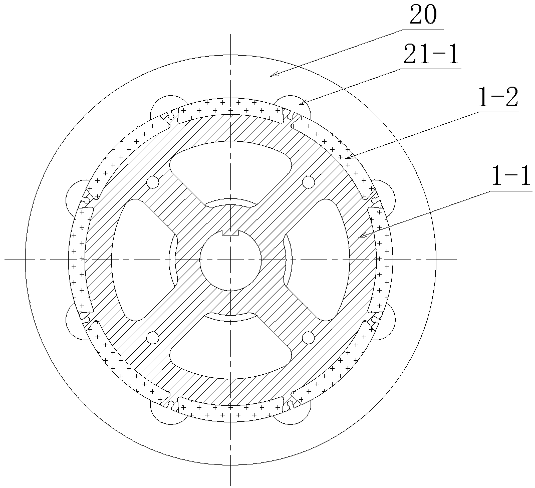
[0022] As shown in the figure, a permanent magnet motor rotor magnetic steel separation device includes a rotor positioning mold 10, the bottom of the rotor positioning mold 10 is installed on a fixed plate 12 through bolts 11, and the center of the upper end surface of the rotor positioning mold 10 is provided with Positioning boss 13; a lower pressing mold 20 is provided directly above the rotor positioning mold 10, and a cylindrical cavity 21 is provided at the lower part of the lower pressing mold 20 around the centerline, and the lower end opening of the cylindrical cavity 21 faces The upper end surface of the rotor positioning mold 10, and the center of the positioning boss 13 is located on the axis extension line of the cylindrical cavity 21, the diameter of the cylindrical cavity 21 is greater than or equal to the diameter of the rotary support body 1-...


PUM


Abstract

A magnetic steel separation device and a separation method for a rotor of a permanent magnet motor are disclosed. That bottom of a rotor positioning mold is mount on a fixing plate through bolts, anda positioning boss is arranged at the center of the upper end face of the rotor position mold. A low pressing die is arrange directly above that rotor positioning die, The lower end opening of the lower cylindrical cavity of the lower pressing mold faces the upper end surface of the rotor positioning mold, and the center of the positioning boss is located on the axial center extension line of thecylindrical cavity. The lower pressing mold is uniformly spaced with a plurality of receiving through grooves around the inner wall of the cylindrical cavity, and the lower pressing mold is driven tomove up and down by a driving part. As that structure design of the invention is ingenious, and the magnetic steel sheet on the rotor of the permanent magnet motor and the rotary support body can be separated quickly without manpower in the separation process, the force applied on the rotor of the permanent magnet motor in the disassembly process is uniform, the damage to the magnetic steel sheetor the rotary support body can be avoided, and the repeated utilization of the magnetic steel sheet or the rotary support body is realized.

Description

technical field [0001] The invention relates to a permanent magnet motor rotor magnetic steel separation device and a separation method, belonging to the field of mechanical processing. Background technique [0002] With the gradual enhancement of people's living standards and environmental protection awareness, electric vehicles have gradually become popular and replaced other means of transportation, and their driving power is mainly provided by electric motors. As the core component of the motor, the permanent magnet motor rotor has a decisive influence on the running quality and service life of the motor, such as figure 1 As shown, the conventional structure of the permanent magnet motor rotor 1 includes a rotary support body 1-1 and a plurality of magnetic steel sheets 1-2 arranged on its surface in the circumferential direction around the rotary support body 1-1, and the plurality of magnetic steel sheets 1-2 include sequentially A plurality of N poles and S poles arr...

Claims


Application Information

Patent Timeline
Patent Type & Authority Applications(China)
IPC IPC(8): H02K15/00
CPCH02K15/0006
Inventor 王宏伟
Owner 徐州给力磁业有限公司
Features
  • R&D
  • Intellectual Property
  • Life Sciences
  • Materials
  • Tech Scout
  • Unparalleled Data Quality
  • Higher Quality Content
  • 60% Fewer Hallucinations
Learn More