Method for protecting a rotation separator from icing, and rotation separator

一种旋转分离器、转子的技术,应用在离心机、机器/发动机、发动机的润滑等方向,能够解决旋转分离器穿流、旋转分离器功率受损、转子的轴承结冰等问题

Active Publication Date: 2018-12-21
HENGST WALTER
View PDF6 Cites 4 Cited by
  • Summary
  • Abstract
  • Description
  • Claims
  • Application Information

AI Technical Summary

Problems solved by technology

Especially when several short trips are carried out in succession, it cannot be ruled out that an ice layer forms in the rotary separator, which prevents the flow through the rotary separator
For example, the gaps between the individual disks of a disc separator may be closed by such ice, or the bearings of the rotor may freeze so that when the internal combustion engine is restarted, the rotary separator either cannot (or is not balanced) set in rotation , or cannot be flowed through as intended, so that the power of the rotary separator may in any case be partially or completely impaired

Method used


Image

  • Method for protecting a rotation separator from icing, and rotation separator
  • Method for protecting a rotation separator from icing, and rotation separator
  • Method for protecting a rotation separator from icing, and rotation separator

Examples


Embodiment Construction

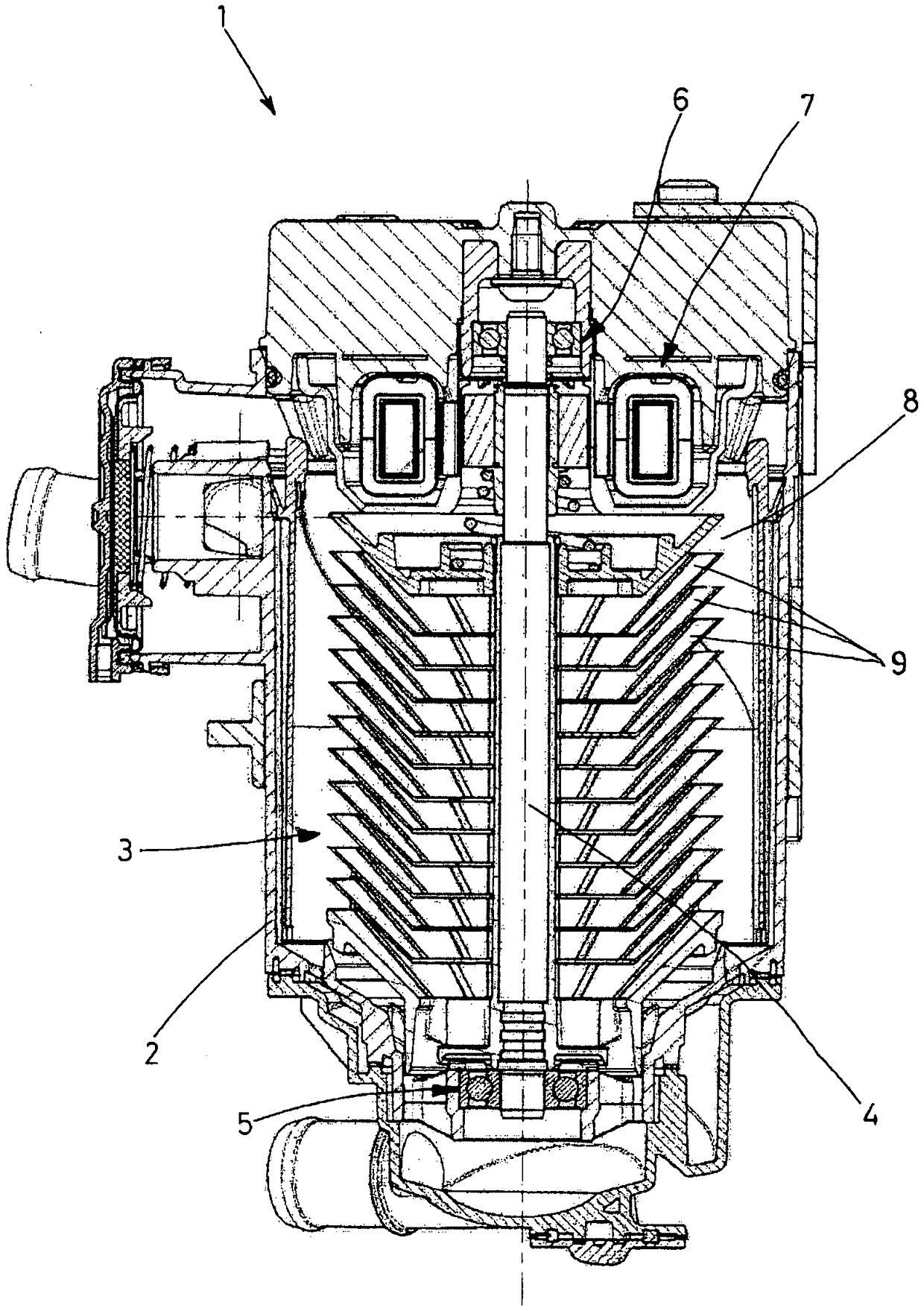
[0026] exist figure 1 In , a rotary separator is designated as a whole by 1, which is designed as a so-called disc separator. The rotary separator 1 has a housing 2 in which a rotor 3 is mounted rotatably about a vertical axis 4 . To this end, the shaft 4 is guided in a lower foot bearing 5 and an upper head bearing 6 . Below said head bearing 6 there is an electric drive unit 7 which directly adjoins an interior space 8 in which there are a plurality of cavity-shaped separation surfaces driven in rotation by means of the shaft 4 which correspond to The land is called Disk 9. The drive unit 7 has a coil which extends concentrically around the shaft 4 .

[0027] Between the disks 9 there remain surface gaps, which can be reduced, for example, to dimensions of less than 0.5 mm, and which are provided with gaps of small cross-sectional size for sealing between the raw side and the clean side Also known as gap seals. Furthermore, it cannot be ruled out that the foot bearing 5...


PUM


Abstract

The invention relates to a method for operating a rotation separator (1), wherein a gas flow, which is laden with solid and / or liquid particles and originates from an internal combustion engine, is fed to a rotationally driven element labeled as a rotor (3), in which method particles are separated from the gas flow and deposited onto the rotor (3), wherein the rotor (3) is operated at a rotationalspeed labeled as an effective rotational speed in such a way that the particles deposited on the rotor (3) are spun off from the rotor (3) as a result of the rotational motion of the rotor (3). According to the invention, after the internal combustion engine has been shut off, the rotor (3) is set into rotation at the effective rotational speed by means of a so-called separate start (A) while theinternal combustion engine is at a standstill. The invention further relates to a rotation separator (1) that is controlled by a control system in such a way that the rotation separator is operated in accordance with said method.

Description

technical field [0001] The invention relates to a method according to the preamble of claim 1 . Background technique [0002] A method of the same type is known from EP 1 532 353 B1. This known method is used to clean the air flow from the crankcase of an internal combustion engine. On the more general principle of centrifugal separators (which can also be designed, for example, as cyclone separators which do not require rotatable parts but instead have a fluid placed in rotation), a rotary separator is a An embodiment variant in which a rotating component is provided, which is accordingly designated as the rotor. In particular, the rotor can have a plurality of separation surfaces arranged one above the other in a stack, wherein such a rotary separator is also referred to as a disk separator in practice. Within the scope of this approach, such a disc separator is always considered and mentioned as an exemplary embodiment of a rotary separator, without the invention being...

Claims


Application Information

Patent Timeline
Patent Type & Authority Applications(China)
IPC IPC(8): F01M13/04F02D41/04B04B9/02B04B5/08
CPCB04B5/08F02D41/042F01M2013/0422F01M2013/0455F02D2200/023F02D2250/08F16N2200/10F16N2250/08B04B5/12B04B9/10F01M13/04F01M2013/0472
Inventor S·罗伯特M·勒尔韦尔
Owner HENGST WALTER
Why Eureka
Try Eureka