Resilient contact terminal

A technology of elastic contact terminals and contact terminals, which is applied in the direction of convex contact, contact parts, emergency contact forms, etc., can solve the problems that switches or thermoelectric components cannot be used, the operating distance is large, and it is not economical. It is easy to reflow soldering, Large operating distance, good heat transfer and heat dissipation

Inactive Publication Date: 2018-12-21
JOINSET
View PDF12 Cites 4 Cited by
  • Summary
  • Abstract
  • Description
  • Claims
  • Application Information

AI Technical Summary

Problems solved by technology

[0008] In addition, if the electrical contact terminal is viewed, it is sandwiched between one object and another object in an elastic manner, thereby being used to form an electrical path between the upper and lower sides, which cannot be applied to, for example, switching For applications such as devices or thermoelectric components
[0009] Moreover, it also has the following disadvantages: it is impossible to economically provide an electrical contact terminal with a low height, a large operating distance, and reliable elasticity and resilience.

Method used


Image

  • Resilient contact terminal
  • Resilient contact terminal
  • Resilient contact terminal

Examples


Embodiment Construction

[0046]Technical terms used in the present invention are only used to describe specific embodiments, and it should be noted that they are not intended to limit the present invention. And, unless specifically defined as other meanings in the present invention, the technical terms used in the present invention should be interpreted as meanings that can be generally understood by those with basic knowledge in the technical field to which the present invention belongs, and should not be interpreted as overly covering meanings or overly narrowed meanings. Furthermore, when technical terms used in the present invention are erroneous technical terms that cannot accurately express the idea of ​​the present invention, they should be replaced with technical terms that can be correctly understood by those skilled in the art. In addition, the general terms used in the present invention must be interpreted according to the content defined in the dictionary or the context of the literature, ...


PUM


Abstract

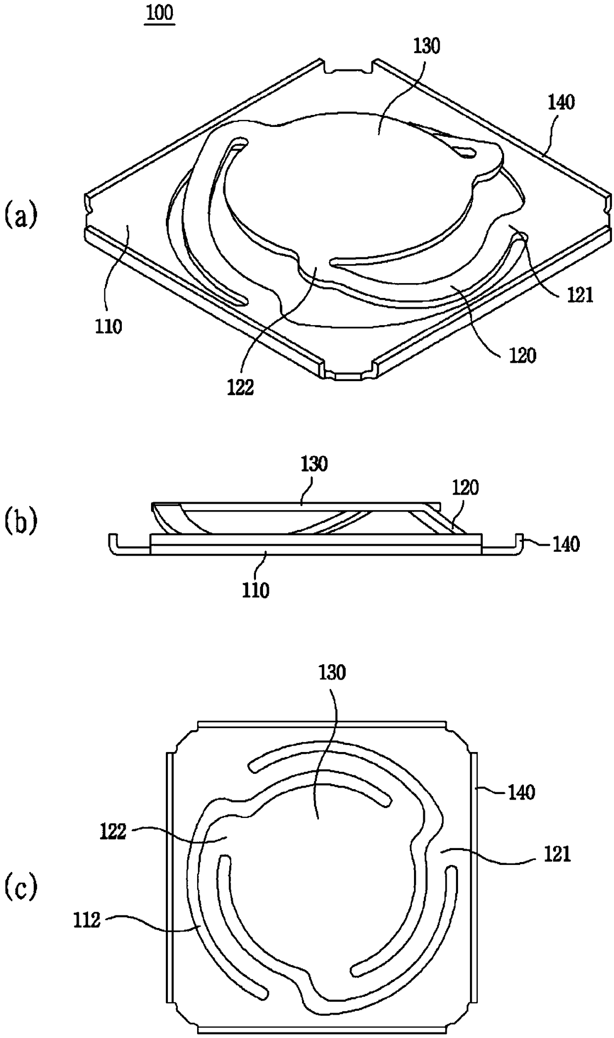
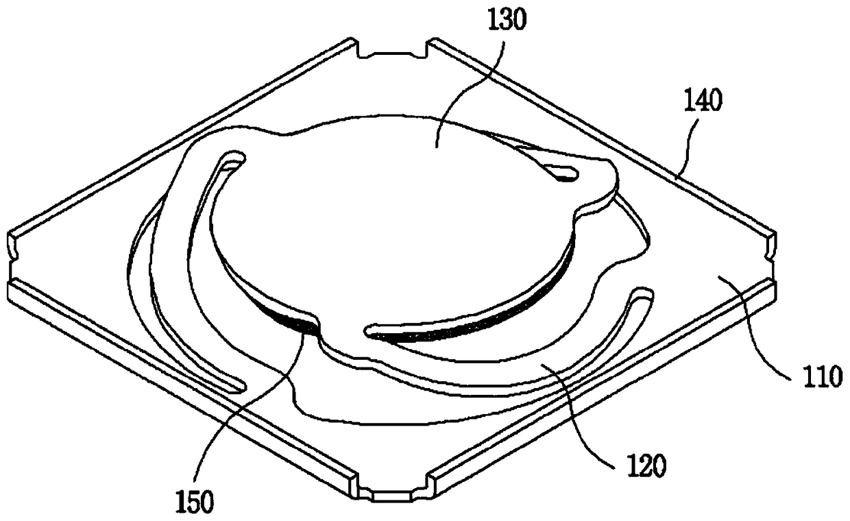
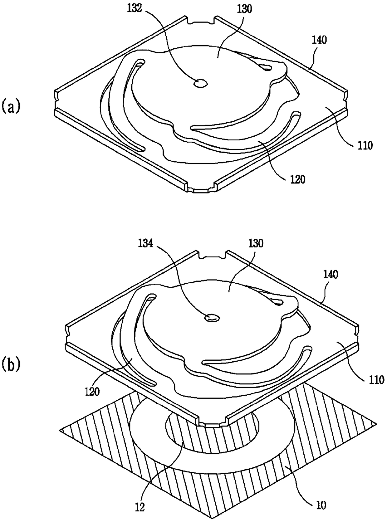
The present invention discloses a resilient contact terminal having a structure that can be applied to various purposes. The contact terminal has: a base; a plurality of bridges of which one end is connected to the base, is spirally wound and extends in upward inclination, and which thus are vertically resilient; and a contact portion connected to the other end of each bridge. A gap portion separates the bridges and the contact portion, and the bridges and the base. The edge of the base is positioned further outward than the edge of the contact portion.

Description

technical field [0001] The present invention relates to an elastic contact terminal, and more particularly, to an elastic contact terminal having a structure applicable to various purposes. Background technique [0002] The surface mount type elastic electrical contact terminal of Korea Granted Patent No. 1644119 applied by the present applicant includes: a board-shaped fixing part, the lower surface of which can be reflow soldered to a circuit board by solder paste, and a board-shaped contact part from which the fixed part is spaced apart from above, and at least a part capable of vacuum pickup is formed on the upper surface, and is smaller in size than the fixed part; A plurality of bridges extending around the edge position are formed, one end of each bridge is arranged opposite to each other, the other end of any one of the bridges is connected to the contact portion, and the other end of the other is arranged on the contact portion. The lower surface of the part, and t...

Claims


Application Information

Patent Timeline
Patent Type & Authority Applications(China)
IPC IPC(8): H01R13/24H01R12/70H01R12/55H05K7/20H05K3/34H01L23/367H05K9/00
CPCH01H13/79H01H2203/002H01H2203/022H01H2203/024H01H2205/004H01H2205/01H01H2215/008H01H2215/024H01L23/36H01R12/57H01R12/712H01R13/245H05K3/341H05K2201/0311H05K2201/10053H05K2201/1031Y02P70/50H01R12/55H01R12/707H01R13/2407F28F3/00H01H1/24H01L23/367H05K1/0203H05K7/2039H05K9/0026H05K2201/10371
Inventor 金善基姜泰万
Owner JOINSET
Why Eureka
Try Eureka