High frequency heating device

A high-frequency heating device, surface wave technology, applied in the direction of electric heating device, microwave heating, electric/magnetic/electromagnetic heating, etc.

Active Publication Date: 2020-12-08
PANASONIC INTELLECTUAL PROPERTY MANAGEMENT CO LTD
View PDF6 Cites 0 Cited by
  • Summary
  • Abstract
  • Description
  • Claims
  • Application Information

AI Technical Summary

Problems solved by technology

The generating unit generates microwaves

Method used


Image

  • High frequency heating device
  • High frequency heating device
  • High frequency heating device

Examples


Embodiment approach 1

[0029]

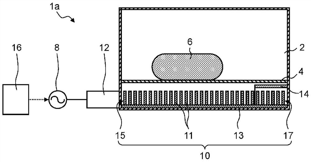
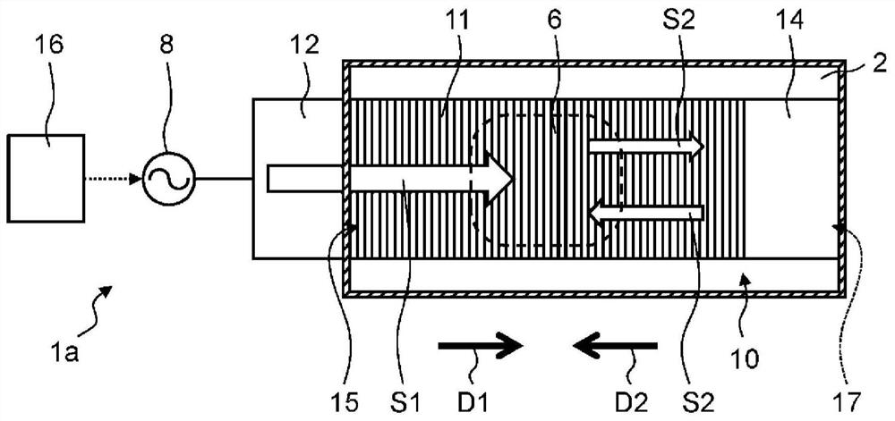
[0030] figure 1 , figure 2 It is a vertical cross-sectional view and a horizontal cross-sectional view schematically showing the structure of the high-frequency heating device 1 a according to Embodiment 1 of the present invention, respectively.

[0031] Such as figure 1 , figure 2 As shown, the high-frequency heating device 1 a has a heating chamber 2 , a generation unit 8 , a surface wave excitation body 10 , a coupling unit 12 , a reflection unit 14 , and a control unit 16 . The high-frequency heating device 1 a is configured to heat the object to be heated 6 placed on the mounting table 4 with microwaves propagating in the surface wave mode on the surface of the surface wave exciter 10 .

[0032] in addition, figure 2 Schematically shows the situation in which microwaves in the surface wave mode propagate on the surface wave excitation body 10, and the heating object 6 is placed on the mounting table 4 (in the figure 2 not shown in the figure).

[0033...

Embodiment approach 2

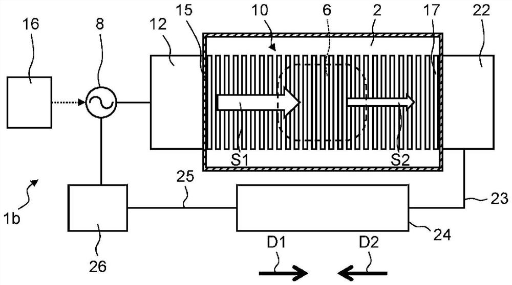
[0056] Regarding the high-frequency heating device 1b according to Embodiment 2 of the present invention, the differences from Embodiment 1 will be mainly described. image 3 It is a cross-sectional view schematically showing the structure of the high-frequency heating device 1b. image 3 Schematically shows the situation in which microwaves in the surface wave mode propagate on the surface wave excitation body 10, and the heating object 6 is placed on the mounting table 4 (in the image 3 not shown in the figure).

[0057] In Embodiment 1, microwaves are reused by reflecting the surface wave S2 that has reached the end side 17 of the surface wave excitation body 10 . On the other hand, in Embodiment 2, microwaves are reused by converting microwaves in the surface wave mode into microwaves in another mode by impedance matching.

[0058] Such as image 3 As shown, the high-frequency heating device 1 b has a matching unit 22 and a converting unit 24 instead of the reflecting ...

Embodiment approach 3

[0070] Regarding the high-frequency heating device 1 c according to Embodiment 3 of the present invention, the difference from Embodiment 2 will be mainly described. Figure 4 It is a cross-sectional view schematically showing the structure of the high-frequency heating device 1c. Figure 4 Schematically shows the microwave propagation of the surface wave mode on the surface wave excitation body 20, and the heating target object 6 on the mounting table 4 (on Figure 4 not shown in the figure).

[0071] Such as Figure 4 As shown, the high-frequency heating device 1 c does not have the conversion unit 24 and the power storage unit 26 , but has a coupling unit 32 instead. The high-frequency heating device 1 c has a surface wave exciter 20 instead of the surface wave exciter 10 . The surface wave exciter 20 has a structure different from that of the surface wave exciter 10 according to the second embodiment. The coupling part 32 corresponds to the second coupling part.

[00...


PUM


Abstract

A high-frequency heating device (1a) has a generating unit (8), a surface wave exciter (10), a first coupling unit (12), and a recycling unit (14). A generating unit (8) generates microwaves. The surface wave exciter (10) has a periodic structure, and heats the object to be heated (6) by propagating microwaves in a surface wave mode. The first coupling part (12) is arranged at one end part (15) of the surface wave excitation body (10). The microwave generated by the generating unit (8) is supplied to the surface wave exciter (10) via the first coupling unit (12). The reuse unit (14) recycles microwaves that have reached the other end (17) of the surface wave excitation body (10) in the microwave propagation direction from one end (15) of the surface wave excitation body (10). It is used for heating the object to be heated (6). According to this aspect, microwaves not absorbed by the object to be heated can be reused for heating the object to be heated.

Description

technical field [0001] The invention relates to high-frequency heating devices such as microwave ovens. Background technique [0002] Conventionally, a high-frequency heating device has been developed that supplies microwaves to a surface wave transmission line to heat an object to be heated such as food. [0003] For example, Patent Document 1 discloses a high-frequency heating device that thaws frozen sushi placed on a surface wave transmission line by directly supplying microwaves to the surface wave transmission line. [0004] prior art literature [0005] patent documents [0006] Patent Document 1: Japanese Patent Application Laid-Open No. 8-166133 Contents of the invention [0007] In the field of high-frequency heating devices, how to efficiently heat an object to be heated has been a long-standing problem. An object of the present invention is to provide a high-frequency heating device that contributes to solving the above-mentioned problems. [0008] A high-...

Claims


Application Information

Patent Timeline
Patent Type & Authority Patents(China)
IPC IPC(8): H05B6/74H05B6/70
CPCH05B6/70H05B6/707
Inventor 冈岛利幸大森义治吉野浩二广部贵纪上岛博幸
Owner PANASONIC INTELLECTUAL PROPERTY MANAGEMENT CO LTD
Why Eureka
Try Eureka