Automatic door controller

A controller and automatic door technology, applied in the direction of motor control, program control, control system, etc., can solve the problems of complex adjustment of automatic door system and inability to guarantee the braking distance

Inactive Publication Date: 2002-09-11
NABLESCO CORP
View PDF1 Cites 2 Cited by
  • Summary
  • Abstract
  • Description
  • Claims
  • Application Information

AI Technical Summary

Problems solved by technology

Without this adjustment of the braking resistor, the required braking distance cannot be guaranteed
Then, it becomes complicated to adjust the automatic door system at the time of installation

Method used


Image

  • Automatic door controller
  • Automatic door controller
  • Automatic door controller

Examples


Embodiment Construction

[0074] Overview of automatic door systems

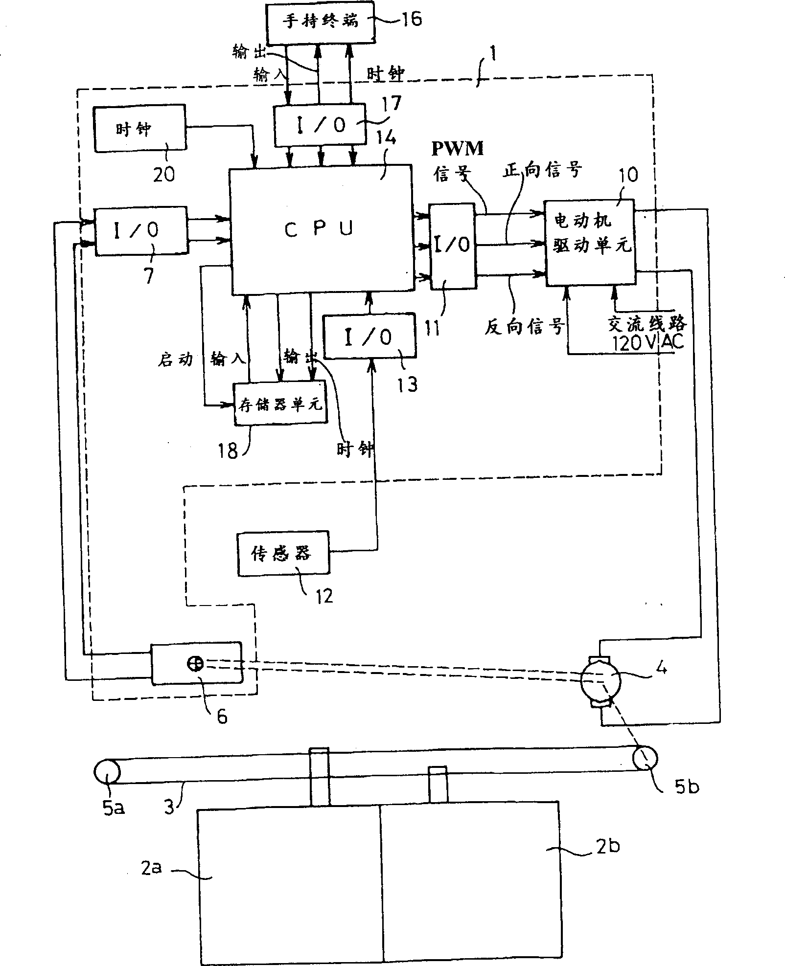
[0075] An automatic door system according to an embodiment of the present invention includes a door 2a and a door 2b, such as figure 1 shown. The doors 2a and 2b slide in opposite directions along linear passages between their positions in which they fully close the doorway (hereinafter referred to as fully closed position) and their positions in which they fully open the doorway (hereinafter referred to as fully open position). The gate 2a is coupled to the upper portion of an endless drive belt 3, and the gate 2b is coupled to the lower portion of an endless drive belt 3. As shown in FIG. The driving belt 3 is wound around the driven pulley 5a and the driving pulley 5b to form a loop between the driven pulley 5a and the driving pulley 5a. The drive pulley 5b is driven by an electric motor (for example, a DC motor 4). Rotation of the motor 4 moves the doors 2a and 2b along respective linear paths in opposite directions between th...


PUM


Abstract

The present invention relates to an automatic door controller for controlling the operation of a motor to open and close a door, comprising: a position control unit for detecting a position of the door in each door operation and generating a signal indicating the door a position representation signal of the position of the motor; a motor drive unit for causing the motor to generate driving force and control force; and a control unit for providing the motor drive unit with a control signal formed according to the position representation signal; wherein the control unit includes output means for generating the control signal for controlling the speed of the door at the position represented by the door position indicating signal such that it is equal to the target speed for that position; the The motor driving unit causes the motor to alternately generate a driving force and a braking force according to the control signal. The automatic door controller of the present invention can control any type of door in a safe and comfortable manner.

Description

technical field [0001] The present invention relates to an automatic door controller for controlling a door of an automatic door system. Background technique [0002] An example of an automatic door system is an automatic sliding door system. For example, when a sliding door slides from a fully closed position to a fully open position, the speed change is controlled in the following manner. First, gradually increase the door speed and, after reaching a relatively high constant speed, maintain that speed. Then, as the door slides to a door position close to the fully open position, the controlled door speed is gradually reduced from a constant speed until the door speed reaches a relatively low speed. Thereafter, the door slides to the fully open position at this rather low speed. Similar control is performed when sliding the door from a fully open position to a fully closed position. [0003] Various types of door speed control have been proposed. For example, Japanese ...

Claims


Application Information

Patent Timeline
IPC IPC(8): E05F15/10E05F15/41E05F15/632G05B19/23H02P29/00
CPCG05B19/232G05B2219/42237G05B2219/43044G05B2219/43071G05B2219/43072G05B2219/43074G05B2219/45242
Inventor 神吉久幸田口直树道本真二大场和博
Owner NABLESCO CORP
Why Eureka
Try Eureka