
Box type combined tool

A combined tool and box-type technology, which is applied to home appliances, suction filters, suction hoses, etc., can solve problems such as difficult disassembly, large space occupation, and aesthetic impact, achieving reliable and stable installation structures and reducing transportation costs , the effect of taking up little space

Pending Publication Date: 2018-12-25
SKYBEST ELECTRIC APPLIANCE SUZHOU CO LTD
View PDF6 Cites 0 Cited by
  • Summary
  • Abstract
  • Description
  • Claims
  • Application Information

AI Technical Summary

Problems solved by technology

Although this method can solve the problem of hose storage to a certain extent, there are still disadvantages such as inconvenient winding, large space occupation, and impact on the packing capacity of the whole machine.
[0003] Second, vacuum cleaners are usually equipped with extension tubes, which are difficult to store due to the size of the extension tubes
In the prior art, the extension tube is usually inserted around the machine head or the dust bucket, but this storage method not only takes up a lot of space, but also affects the appearance
[0004] Third, the conventional hasp of wet and dry vacuum cleaners generally consists of three parts, such as the technical solution disclosed in the US patent document US8567828 announced on October 29, 2013, including a hasp, a connecting rod and a hasp seat, and its structure is relatively complicated. The assembly is cumbersome, and the size of the connecting rod and the self-locking angle need to be considered inside the buckle. The overall size of the buckle is relatively large, which affects the packing volume of the whole machine and the manufacturing cost of materials
[0005] Fourth, the strap buckle structure of the vacuum cleaner in the prior art is not easy to disassemble and has poor durability
In the prior art, in order to make the battery chamber cover have an automatic reset function, it is necessary to add a torsion spring or a tension spring structure, but this structure is more complicated, the cost is high, and the assembly process is cumbersome, which affects the assembly efficiency

Method used


Image

  • Box type combined tool
  • Box type combined tool
  • Box type combined tool

Examples


Embodiment Construction

[0070] The present invention will be described in detail below in conjunction with specific embodiments shown in the accompanying drawings. However, these embodiments do not limit the present invention, and any structural, method, or functional changes made by those skilled in the art according to these embodiments are included in the protection scope of the present invention.

[0071] It should be understood that in the description of specific embodiments of the present invention, terms such as "first" and "second" are used for description purposes only, and cannot be understood as indicating or implying relative importance or implicitly indicating the indicated technology number of features. Thus, a feature defined as "first" or "second" may explicitly or implicitly include one or more of these features.

[0072] In the specific implementation of the present invention, unless otherwise clearly stipulated and limited, terms such as "connected" and "connected" should be under...


PUM


Abstract

The invention discloses a box type combined tool. The box type combined tool comprises a machine head assembly and a dust collecting bucket assembly, wherein the machine head assembly comprises a vacuum generator, a filter and a cover body device; the box type combined tool also comprises a bottle opener assembly arranged on the cover body assembly, the bottle opener assembly is provided with a bottle opening member used for opening a bottle, the bottle opener assembly comprises at least two fixing arms extending in the direction of the machine head assembly, the tail ends of the fixing arms are bent upward, the cover body device is provided with a bottle opener assembly mounting part, the bottle opener assembly mounting part comprises through grooves and positioning grooves, the number ofthe through grooves corresponds to the number of the fixing arms, the positioning grooves are arranged at the upper ends of the through grooves, the fixing arms extend into the cover body device through the through grooves, and the tail ends of the fixing arms abut against the positioning grooves. The box type combined tool is provided with the bottle opener assembly, so that the use range of thebox type combined tool is wider.

Description

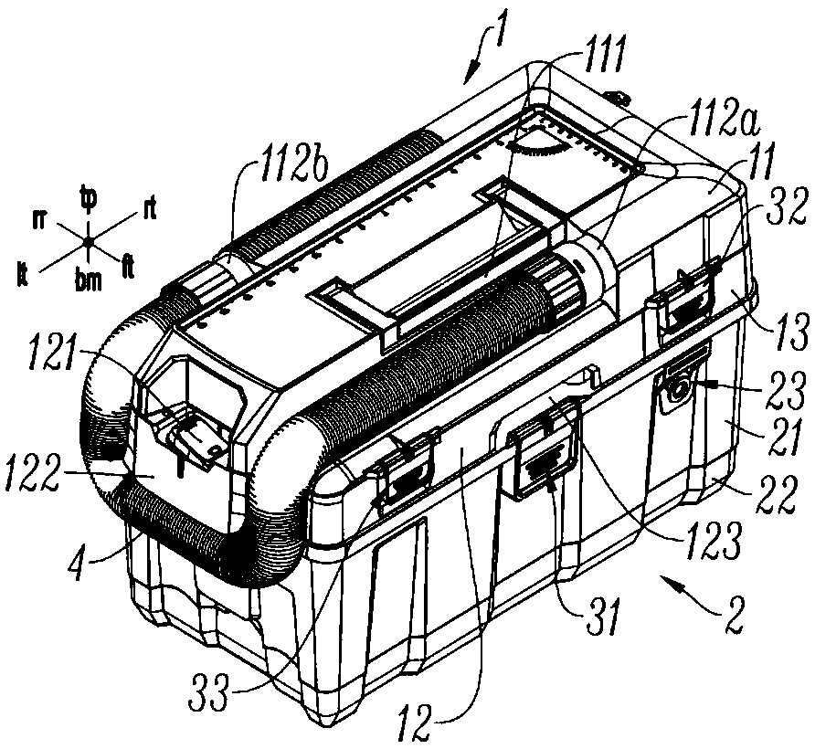
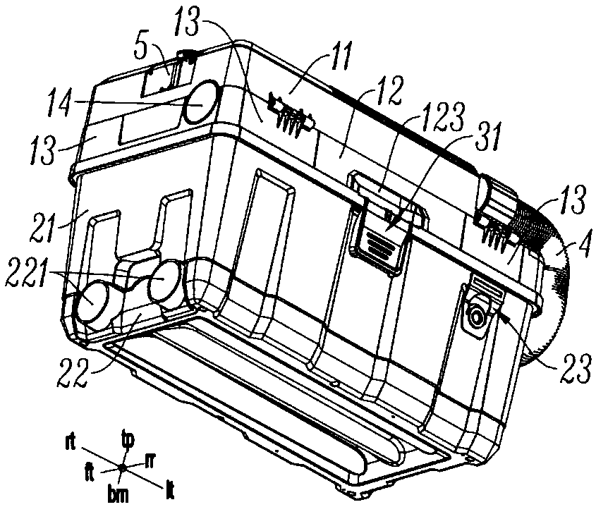
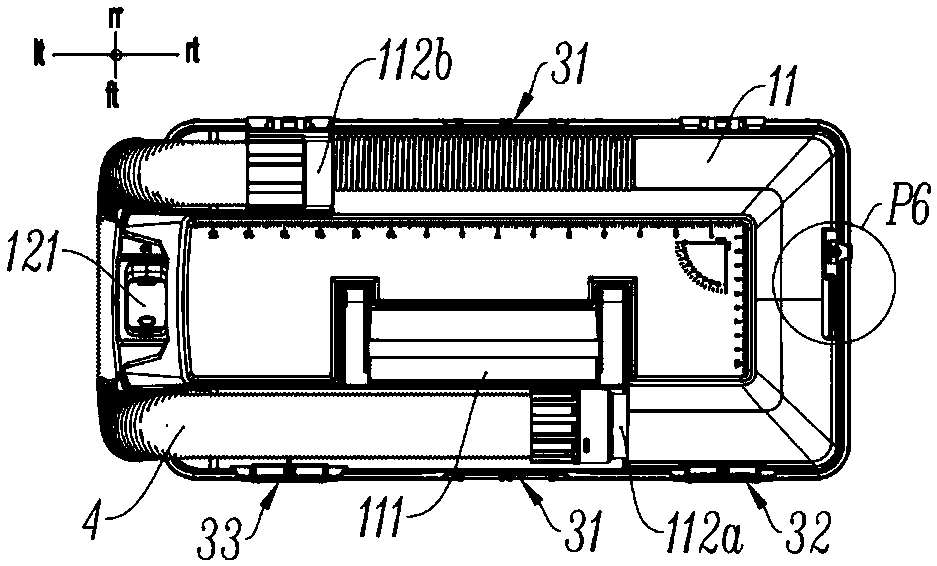
technical field [0001] The invention relates to a box-type combined tool, in particular to a box-type blow-suction dual-purpose machine or a box-type vacuum cleaner. Background technique [0002] First, when traditional wet and dry vacuum cleaners are stored, the hose is usually coiled around the machine head or the dust bucket, and the hose is fixed by a hose clamping device. Although this method can solve the problem of hose storage to a certain extent, there are still disadvantages such as inconvenient winding, large space occupation, and impact on the packing capacity of the whole machine. [0003] Second, vacuum cleaners are usually equipped with extension tubes, which are difficult to accommodate due to the size of the extension tubes. In the prior art, the extension tube is usually inserted around the machine head or the dust bucket, but this storage method not only takes up a lot of space, but also affects the appearance. [0004] Third, the conventional hasp of we...

Claims


Application Information

Patent Timeline
Patent Type & Authority Applications(China)
IPC IPC(8): A47L5/12A47L9/00A47L9/10A47L9/24A47L9/28
CPCA47L5/12A47L9/00A47L9/106A47L9/242A47L9/248A47L9/2884
Inventor 卞小贤刘海平吴淼戴雄李进王峰
Owner SKYBEST ELECTRIC APPLIANCE SUZHOU CO LTD
Learn More