
Optical fiber connector assembly machine

A fiber optic connector and assembly machine technology, applied in assembly machines, metal processing, metal processing equipment, etc., can solve problems such as poor assembly efficiency and yield, difficulty in ensuring feeding accuracy, and easy blockage of springs, etc., to improve assembly Accuracy, processing efficiency and yield are high, and the effect of reducing machine failure rate

Inactive Publication Date: 2018-12-25
吴美珍
View PDF5 Cites 13 Cited by
  • Summary
  • Abstract
  • Description
  • Claims
  • Application Information

AI Technical Summary

Problems solved by technology

The optical fiber connector is assembled by the front shell, optical fiber core, rubber tube, spring and rear shell. Due to the small size of each part, it is difficult to ensure the accuracy of feeding each part, especially the spring is easy to block during the falling process, which has assembly efficiency and The problem of poor yield

Method used


Image

  • Optical fiber connector assembly machine
  • Optical fiber connector assembly machine
  • Optical fiber connector assembly machine

Examples


Embodiment Construction

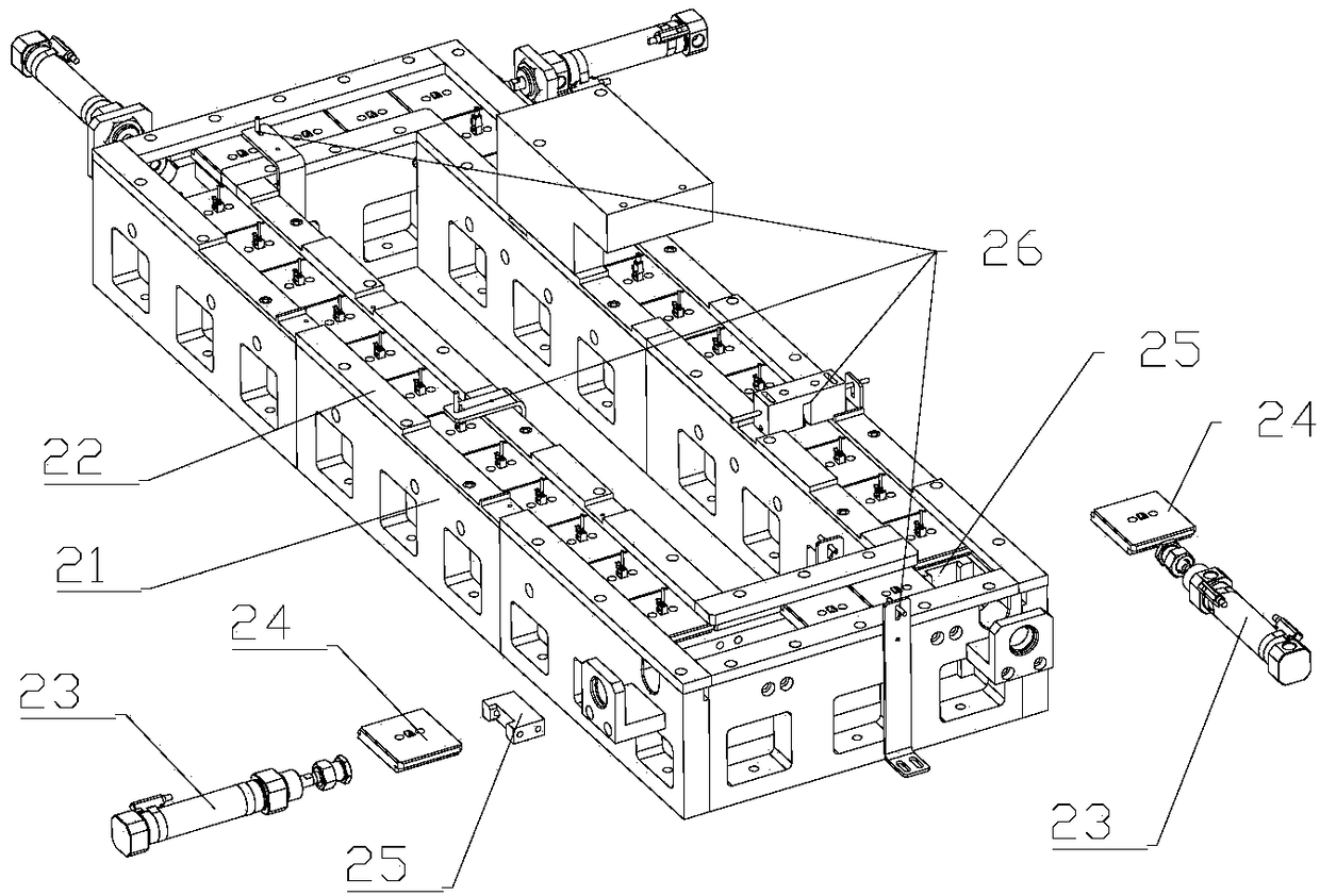
[0036] Combine below Figure 1-Figure 22 The present invention is further described.

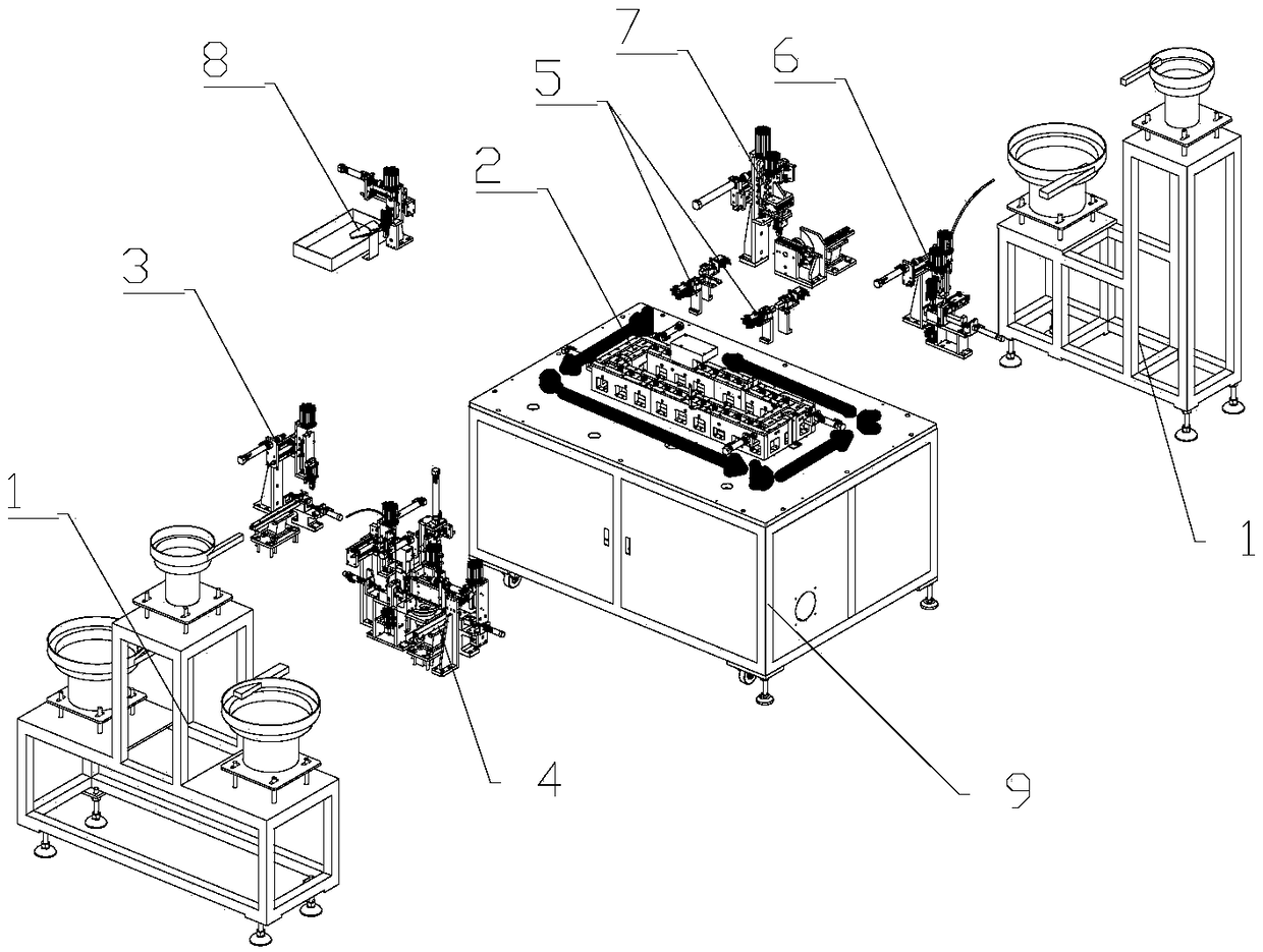
[0037] Such as Figure 1-Figure 22 The optical fiber connector assembly machine shown includes a frame 9 and a vibrating feeding assembly 1 on it, a carrier rectangular circulation device 2, a front shell feeding device 3, a rubber hose and an optical fiber core assembly feeding device 4, and a guiding mechanism 5. Spring loading device 6, back shell feeding device 7 and finished product handling device 8.

[0038] The optical fiber connector is assembled by the front shell e, the optical fiber core f, the rubber tube g, the spring h and the rear shell i.

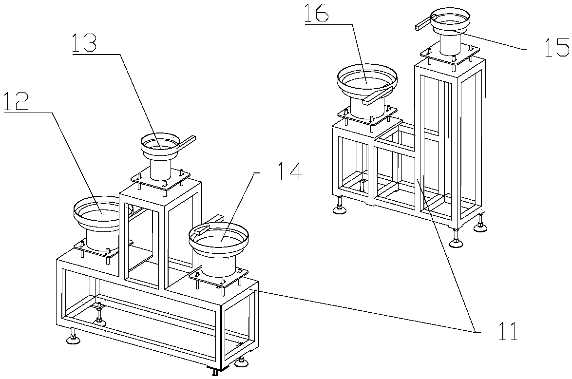
[0039] The vibrating feeding assembly 1 includes a fixed chassis 11 and a front shell vibrating feeding tray 12 on it, a rubber hose vibrating feeding tray 13, an optical fiber core vibrating feeding tray 14, a spring vibrating feeding tray 15 and a rear shell vibrating feeding tray 16. The front shell vibrating feeding tray 12 is used...


PUM


Abstract

The invention relates to the technical field of production of optical fiber connectors. An optical fiber connector assembly machine comprises a rack and further comprises a vibration feeding assembly,a carrier rectangular circulation device, a front shell feeding device, a rubber pipe, an optical fiber core assembly feeding device, a guiding mechanism, a spring installing device, a shell feedingdevice and a finished product carrying device which are arranged on the rack. The optical fiber connector assembly machine has the advantages of fully automatically completing assembly of a front shell, an optical fiber core, a rubber pipe, a spring and a back shell, and the processing efficiency and the yield are high.

Description

technical field [0001] The invention relates to the technical field of production of optical fiber connectors. Background technique [0002] Optical fiber connectors are mainly used to realize the connection of optical fibers. The optical fiber connector is assembled from the front shell, optical fiber core, rubber tube, spring and rear shell. Due to the small size of each part, it is difficult to ensure the accuracy of feeding each part. The problem of poor yield. Contents of the invention [0003] The object of the present invention is to provide an optical fiber connector assembly machine which can automatically and efficiently complete the assembly of optical fiber connectors. [0004] In order to achieve the above object, the present invention adopts the following technical solutions: optical fiber connector assembly machine, including the frame and the vibrating feeding assembly on it, carrier rectangular circulation device, front shell feeding device, rubber hose ...

Claims


Application Information

Patent Timeline
Patent Type & Authority Applications(China)
IPC IPC(8): B23P21/00B23P19/00
CPCB23P19/001B23P19/002B23P21/004
Inventor 吴美珍
Owner 吴美珍
Learn More