Combined prefabricated base board and composite floor slab structure and composite floor slab construction method

A technology for superimposing floors and bottom slabs, which is applied in the direction of floors, building components, building structures, etc. It can solve the problems of inability to adjust the bending resistance, shear resistance and crack resistance, inconvenient prefabricated production, transportation and installation, and many types of prefabricated bottom slabs. problems, to achieve the effect of simplifying prefabricated production, avoiding heavy lifting, and expanding the applicable span range

Pending Publication Date: 2018-12-25
邹胜斌
View PDF9 Cites 10 Cited by
  • Summary
  • Abstract
  • Description
  • Claims
  • Application Information

AI Technical Summary

Problems solved by technology

[0005] The present invention firstly provides a combined prefabricated bottom slab, which solves the problem that the bending resistance, shear resistance and crack resistance cannot be adjusted after the prefabricated bottom slab of the existing laminated floor is formed; and due to the difference in span and load, there are many types of prefabricated bottom slabs, which is not convenient for prefabricated production , transportation and installation; and when the span is large, the thickness and reinforcement increase, which is not economical and is also restricted by the lifting capacity

Method used


Image

  • Combined prefabricated base board and composite floor slab structure and composite floor slab construction method
  • Combined prefabricated base board and composite floor slab structure and composite floor slab construction method
  • Combined prefabricated base board and composite floor slab structure and composite floor slab construction method

Examples


Embodiment Construction

[0041] The present invention will be further described below in conjunction with accompanying drawing.

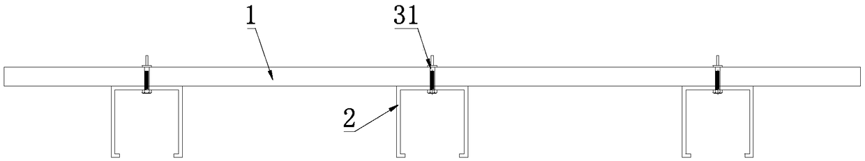
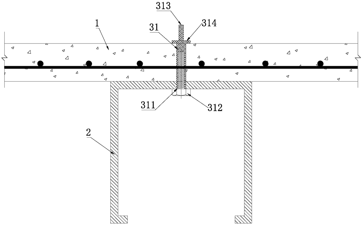
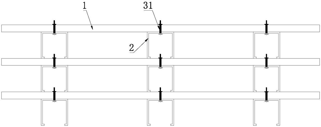
[0042] The combined prefabricated bottom plate of the present invention includes a prefabricated bottom plate 1 and a support member 2, and the prefabricated bottom plate 1 is equipped with reinforcement, that is, the prefabricated bottom plate 1 is provided with a reinforcement mesh. The prefabricated bottom slab 1 is a reinforced concrete slab or a prestressed reinforced concrete slab. Connectors are embedded in the prefabricated floor 1. The upper ends of the connectors pass through the upper surface of the prefabricated floor 1, and the parts that pass through the upper surface of the prefabricated floor 1 form shear studs. The new concrete on the surface, that is, the shear connection between the laminated layers of post-cast concrete. Specifically, such as Figure 1~5 As shown, the connector is a sleeve 31, and the part passing through the upper surface of the prefa...


PUM


Abstract

The invention discloses a combined prefabricated base board and composite floor slab structure and a composite floor slab construction method and relates to the field of building structures. The problems are solved that the bending, shearing and cracking resistance capability of prefabricated base boards of existing composite floor slabs cannot be adjusted after forming; a variety of prefabricatedbase boards exist and are inconvenient to prefabricate, produce, transport and install; when spans are larger, the thickness is increased, the cost is high and hoisting is difficult. According to theadopted technical scheme, a combined prefabricated base board comprises a prefabricated base board body and a supporting part, a connector is embedded in the prefabricated base board body, the upperend of the connector penetrates out of the upper surface of the prefabricated base board, any one of the upper side and the lower side of the prefabricated base board body is connected with the supporting part, and the supporting part is detachably connected with the connector. The upper surface of the prefabricated base board body is poured with a later-poured concrete composite layer to form thecomposite floor slab structure. The prefabricated base board body is connected with the supporting part and can be made thinner, the bending resistance capability of the prefabricated base board bodyat a construction stage can also be adjusted, the types of combined prefabricated base boards are decreased, formwork-free construction is achieved, and development of prefabricated buildings is promoted.

Description

technical field [0001] The invention relates to the technical field of building structures, in particular to a combined prefabricated floor and laminated floor structure of an assembled building, and a construction method for the laminated floor. Background technique [0002] The laminated floor is a floor form that combines the prefabricated base plate and the post-cast concrete laminated layer. The prefabricated floor with a certain thickness is combined with the upper post-cast concrete laminated layer to form an integral structure, which bears the force together. The laminated slab has the integrity of the cast-in-place slab, and has the advantages of high rigidity, saving formwork, shortening the construction period, etc., so it is widely used in prefabricated buildings. [0003] The thickness of the prefabricated bottom slab of the existing laminated floor slab is generally 5-9cm, which is suitable for the floor slab whose span range is not more than 6m, and the use i...

Claims


Application Information

Patent Timeline
Patent Type & Authority Applications(China)
IPC IPC(8): E04B5/38
CPCE04B5/38
Inventor 邹胜斌
Owner 邹胜斌
Why Eureka
Try Eureka