A fault signal analysis method based on complex wavelet modulus maxima connection line

A modulo maximum, fault signal technology, applied in complex mathematical operations, special data processing applications, instruments, etc., can solve problems such as poor directionality, distorted transformation results, and no reasonable theoretical basis, achieving simple steps and strong practicability effect of function

Inactive Publication Date: 2018-12-25
XIAN UNIV OF SCI & TECH
View PDF2 Cites 0 Cited by
  • Summary
  • Abstract
  • Description
  • Claims
  • Application Information

AI Technical Summary

Problems solved by technology

At present, the real wavelet is the first choice for ranging. Of course, the real wavelet still has many advantages, such as compact support, orthogonality, high vanishing moment, accurate reconstruction, approximate symmetry, etc., but its defects mainly have three major aspects: translation sensitivity, direction Poor sex, lack of phase information
[0003] When analyzing signals, translation sensitivity, poor directionality, and unresolved frequency domain will cause distortion of the transformation results, and the singularity of the signal cannot be accurately extracted due to oscillations
The translation sensitivity of real wavelet will lead to poor effect of real wavelet analysis on translation signal
Due to the uncertainty of intercepting the actual signal, it is difficult to grasp the time of intercepting the signal, especially when selecting the power signal, there is no reasonable theoretical basis for how to select the signal point, so that the signal selection is random
If the real wavelet is used to analyze the signal, the accuracy of the result is unpredictable, especially for the signal that needs to be analyzed multiple times. Since the selection of signal points is different when analyzing the fault signal, there is a certain difference in each analysis result. The result It is difficult to judge the difference

Method used


Image

  • A fault signal analysis method based on complex wavelet modulus maxima connection line
  • A fault signal analysis method based on complex wavelet modulus maxima connection line
  • A fault signal analysis method based on complex wavelet modulus maxima connection line

Examples


specific Embodiment approach

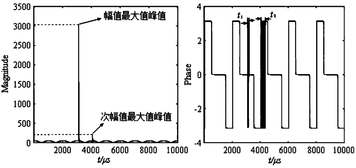
[0081] Specific implementation method: now the three-phase current fault signal is used as the test signal for analysis, and the algorithm flow of the entire singularity analysis is as follows Figure 5 shown. in Figure 4 (a) is the three-phase current fault waveform diagram in the specific embodiment; (b) the A-phase waveform diagram intercepted by the three-phase current fault in the specific embodiment, the fault time is 0.035s, and the whole simulation time is 0.1s, such as Figure 4 (a) shown. Take 500 points between 3500 and 4000 from the A-phase current traveling wave in the three-phase current waveform, such as Figure 4 As shown in (b), use four Gaussian complex wavelets cgau2, cgau4, cgau6, and cgau8 to transform the intercepted current waveform signal, draw the signal modulus maximum connection line, and then calculate the Lipschitz index of the corresponding point. After the four transformations The modulus maxima connecting lines are shown in Image 6 (a), (b...


PUM


Abstract

The invention discloses a fault signal analysis method based on a complex wavelet modulus maximum connecting line, which comprises steps that: the fault signal is obtained and processed by continuouswavelet transform; the vanishing moment of complex wavelet is optimized and the vanishing moment of complex wavelet is judged to be optimal; then the order n of vanishing moment is chosen to be greater than Lipschitz exponent alpha and the complex wavelet transform is carried out; the modulus maxima of continuous wavelet transform coefficients are plotted; the singular point x0 is determined alongthe modulus maxima connection line, and the corresponding slope of log2 | Wf (s, k) | along the modulus maxima connection line converging to x0 is calculated, which slope is alpha + 1 / 2, so that theLipschitz exponent alpha at x0 point is obtained. Compared with the prior art, the invention has strong practical function, simple steps and can be extended to the singularity analysis of other signals.

Description

technical field [0001] The invention relates to the technical field of fault signal analysis, in particular to a fault signal analysis method based on complex wavelet modulus maxima connection. Background technique [0002] As an effective and powerful mathematical analysis tool, wavelet transform has a good application prospect in the analysis of transient signals. At present, the real wavelet is the first choice for ranging. Of course, the real wavelet still has many advantages, such as compact support, orthogonality, high vanishing moment, accurate reconstruction, approximate symmetry, etc., but its defects mainly have three major aspects: translation sensitivity, direction Poor performance and lack of phase information. [0003] When analyzing the signal, translation sensitivity, poor directionality, and unresolved frequency domain will cause distortion of the transformation result, and the singularity of the signal cannot be accurately extracted due to oscillation. Th...

Claims


Application Information

Patent Timeline
Patent Type & Authority Applications(China)
IPC IPC(8): G06F17/14
CPCG06F17/148
Inventor 汪梅张佳楠张国强徐长丰牛钦翟珂王刚
Owner XIAN UNIV OF SCI & TECH
Why Eureka
Try Eureka