
A battery two-phase heat dissipation device based on the heat pipe principle and a heat dissipation method thereof

A technology of heat pipe principle and heat dissipation device, applied in the direction of secondary batteries, circuits, electrical components, etc., can solve the problems of limited heat dissipation capacity, do not pay attention to the heat export problem of a single battery, increase the complexity of the system, etc., and achieve the effect of effective heat dissipation

Pending Publication Date: 2018-12-25
CHINA ELECTRONICS TECH GROUP CORP NO 16 INST
View PDF0 Cites 14 Cited by
  • Summary
  • Abstract
  • Description
  • Claims
  • Application Information

AI Technical Summary

Problems solved by technology

[0004] The cooling methods of existing battery packs mainly adopt air cooling and liquid cooling. The air cooling structure is simple and reliable, but its heat dissipation capacity is limited. Heat dissipation requirements; liquid cooling has a higher heat dissipation capacity than air cooling, but it needs to be equipped with a cooling water circulation circuit, and these two heat dissipation methods are for the overall battery pack heat dissipation, and do not pay attention to the heat output of a single battery
Although there are papers and patents that use heat pipe solutions to solve the heat export of a single battery, the solution is to provide a heat pipe for a single battery, and the heat pipes operate independently. For the entire battery pack, hundreds of heat pipes are required. This undoubtedly increases the complexity of the system and reduces the reliability of the entire battery system

Method used


Image

  • A battery two-phase heat dissipation device based on the heat pipe principle and a heat dissipation method thereof
  • A battery two-phase heat dissipation device based on the heat pipe principle and a heat dissipation method thereof
  • A battery two-phase heat dissipation device based on the heat pipe principle and a heat dissipation method thereof

Examples


Embodiment Construction

[0026] The present invention will be further described below in conjunction with accompanying drawing:

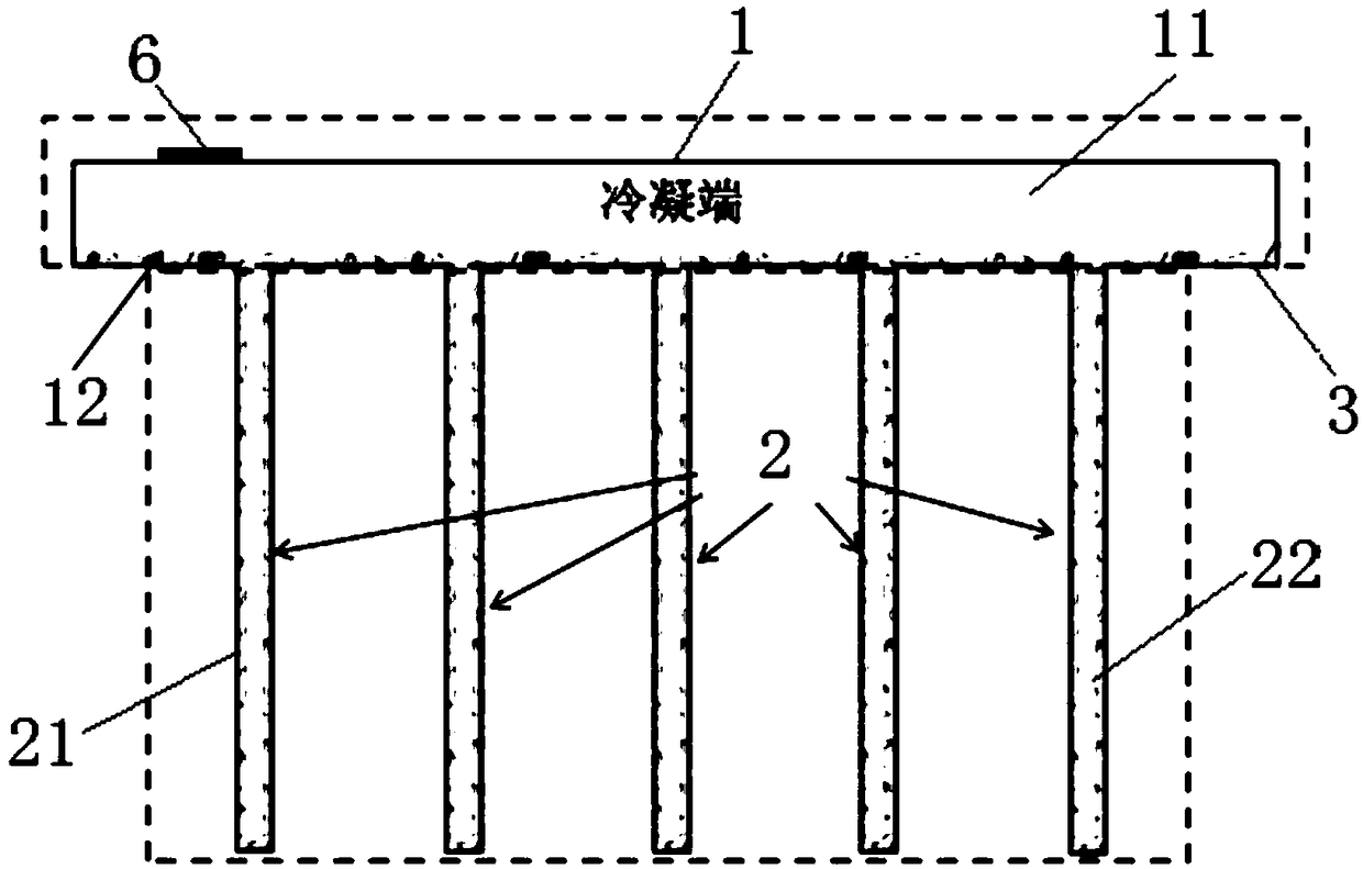
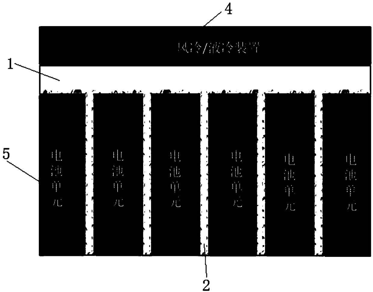
[0027] Such as Figure 1-Figure 4 The shown battery two-phase heat dissipation device based on the heat pipe principle includes a condensing end 1 and several evaporating ends 2 arranged at the bottom of the condensing end 1 . The condensation end 1 is a rectangular cavity structure. The length and number of evaporation ends 2 can be adjusted according to the number of battery cells 5 . The evaporating end 2 is a sheet structure, the upper end of the evaporating end 2 is connected to the bottom of the condensing end 1, and the cavity of the evaporating end 2 and the cavity of the condensing end 1 are connected. When in use, a battery unit 5 is respectively placed between two adjacent evaporation ends 2 , and the left and right side walls of the battery unit are attached to the side walls of the two evaporation ends 2 respectively. At the same time, one battery unit 5 is ...


PUM


Abstract

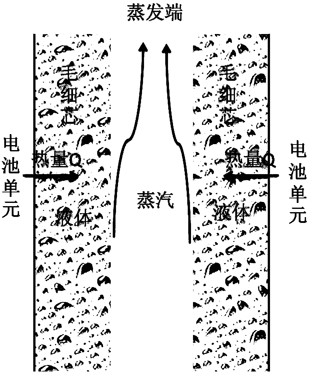
The invention relates to a battery two-phase heat dissipation device based on the heat pipe principle and a heat dissipation method thereof. The device comprises a condensing end and a plurality of evaporating ends arranged at the bottom of the condensing end. The condensing end comprises a condensing chamber and a first capillary core arranged at the bottom of the inner side of the condensing chamber. Each evaporating end includes an evaporation chamber communicating with the condensing chamber and a second capillary core arranged on the inner wall of the evaporating chamber. The top of the condensing chamber is provided with a heat dissipation mechanism. As can be seen from the above technical proposal, the invention adopts the principle of heat pipe, utilizes the phase change heat transfer of the working medium, converts the heat of the battery unit into the phase change latent heat of a working medium charged in the device, and makes the phase change latent heat be rapidly led outalong the evaporatiing ends into the condensing end, and carries out heat exchange with an external heat dissipation device at the condensing end, thereby realizing the effective heat dissipation of asingle battery unit.

Description

technical field [0001] The invention relates to the technical field of electric vehicle battery heat dissipation, in particular to a battery two-phase heat dissipation device based on the heat pipe principle and a heat dissipation method thereof. Background technique [0002] Through the analysis of a large number of test data, it is found that the influence of temperature on battery performance is very significant. Taking the most suitable lithium iron phosphate battery for vehicles at this stage as an example, its most suitable working temperature range is between 20-25°C. When it is higher than 45°C, the discharge capacity will be greatly increased, and the battery life will be significantly shortened. When the temperature is lower than 0°C, the battery will have the risk of explosion and combustion. When the battery temperature is lower than 0°C, the charging performance of the battery will be seriously affected. Therefore, the charging and discharging efficiency of the ...

Claims


Application Information

Patent Timeline
Patent Type & Authority Applications(China)
IPC IPC(8): H01M10/613H01M10/625H01M10/6552H01M10/6569
CPCH01M10/613H01M10/625H01M10/6552H01M10/6569Y02E60/10
Inventor 陈建辉张志同陈维兵鲍桐张忠政葛磊
Owner CHINA ELECTRONICS TECH GROUP CORP NO 16 INST
Learn More