
Pulse generator, pulse generation method and electronic device

A pulse generator and pulse width technology, applied in the field of computer communication, can solve the problems of low resolution and small range

Active Publication Date: 2018-12-25
ZHENGZHOU YUNHAI INFORMATION TECH CO LTD
View PDF6 Cites 3 Cited by
  • Summary
  • Abstract
  • Description
  • Claims
  • Application Information

AI Technical Summary

Problems solved by technology

However, the duty cycle of the output pulse of the charge pump circuit is generally about 45% to 60%, the controllable range is not large, and the operable resolution is not high

Method used


Image

  • Pulse generator, pulse generation method and electronic device
  • Pulse generator, pulse generation method and electronic device
  • Pulse generator, pulse generation method and electronic device

Examples


Embodiment Construction

[0032] In order to enable those skilled in the art to better understand the solution of the present application, the technical solution in the embodiment of the application will be clearly and completely described below in conjunction with the accompanying drawings in the embodiment of the application. Obviously, the described embodiment is only It is a part of the embodiments of this application, not all of them. Based on the embodiments in this application, all other embodiments obtained by persons of ordinary skill in the art without making creative efforts belong to the scope of protection of this application.

[0033] The terms "first", "second", "third", "fourth", etc. (if any) in the specification and claims of the present application and the above drawings are used to distinguish similar objects, and not necessarily Used to describe a specific sequence or sequence. It is to be understood that the data so used are interchangeable under appropriate circumstances such th...


PUM


Abstract

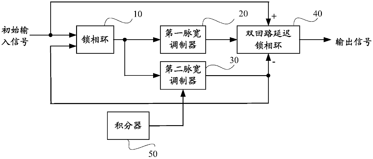
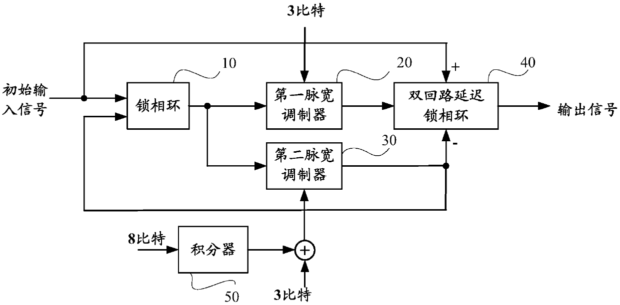
A pulse generator includes a phase-locked loop, a first pulse width modulator, a second pulse width modulator, a dual-loop delay phase-locked loop, and an integrator, wherein the phase-locked loop isconnected with the first pulse width modulator and the second pulse width modulator, respectively, so that the first pulse width modulator and the second pulse width modulator digitally modulate the positive and negative edges of the output signal of the phase-locked loop, respectively, to realize coarse adjustment of the pulse width. The integrator is connected with the second pulse width modulator for modulating the negative edge of the input signal of the second pulse width modulator to realize fine adjustment of the pulse width, and then the output signal of the pulse width modulator is fed back to the phase-locked loop through the dual-loop delay phase-locked loop to form a closed loop so as to synchronize with the input signal and output the pulse signal. The duty cycle of the pulsesignal has a larger output range and a higher resolution. The present application also discloses a pulse generation method and an electronic device.

Description

technical field [0001] The present application relates to the field of computer communication, in particular to a pulse generator, a pulse generating method and electronic equipment. Background technique [0002] Pulse Width Modulation (Pulse Width Modulation, PWM) is a technology that converts a signal into a pulse. The period of the converted pulse is fixed, but the duty cycle (Duty Cycle) tends to change with the size of the signal. [0003] In the application of high-frequency circuits, it is often necessary to calibrate the duty cycle, especially in a system using double data rate synchronous dynamic random access memory (DDR, double data rate), it is necessary to calibrate the duty cycle of the signal to 50%. In some applications, such as circuit applications for adjusting fan speed, it is also necessary to provide various pulse signals with different duty ratios. [0004] The prior art provides a programmable charge pump circuit to calibrate the duty ratio and provid...

Claims


Application Information

Patent Timeline
Patent Type & Authority Applications(China)
IPC IPC(8): H03L7/107
CPCH03L7/1075
Inventor 林冠宇
Owner ZHENGZHOU YUNHAI INFORMATION TECH CO LTD
Learn More