
Multifunctional shoe rack

A multi-functional, shoe rack technology, applied in the field of shoe racks, can solve the problems of time-consuming, troublesome, unpleasant smell, etc., and achieve the effects of stable rotation and improved accuracy

Active Publication Date: 2018-12-28
山东宜和宜美家居科技有限公司
View PDF15 Cites 1 Cited by
  • Summary
  • Abstract
  • Description
  • Claims
  • Application Information

AI Technical Summary

Problems solved by technology

[0002] When entering a room in a family, for reasons of sanitation, it is often necessary to change shoes, and the shoes changed are often very dirty. If the shoes are cleaned, it will be very troublesome and time-consuming; in addition, the shoes worn by people with smelly feet Put it on the shoe rack, it smells very bad
Traditional shoe racks can only be used to place shoes, but cannot effectively clean and deodorize shoes

Method used


Image

  • Multifunctional shoe rack
  • Multifunctional shoe rack
  • Multifunctional shoe rack

Examples


Embodiment 1

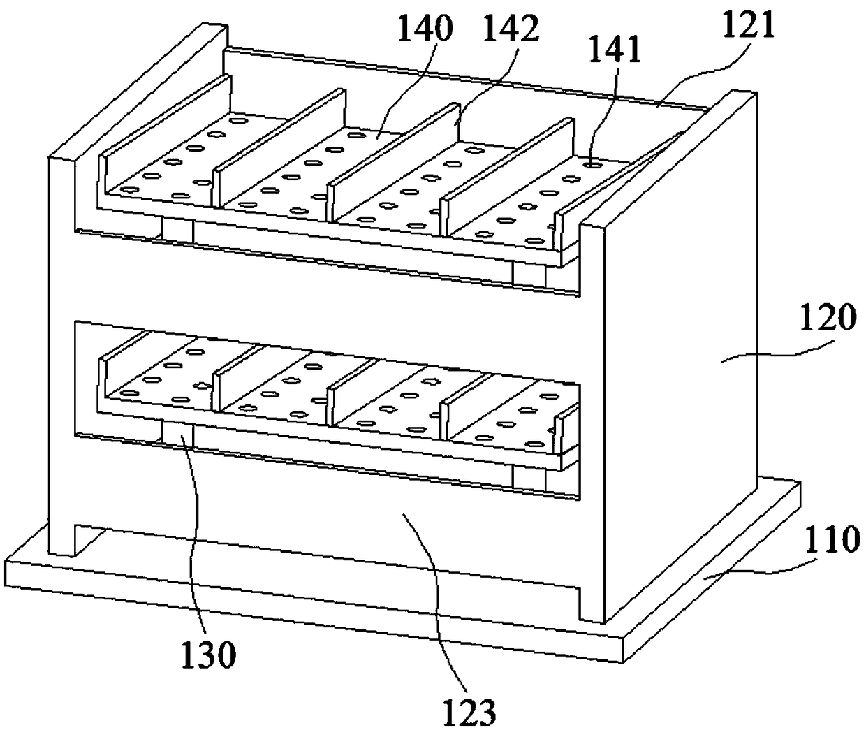
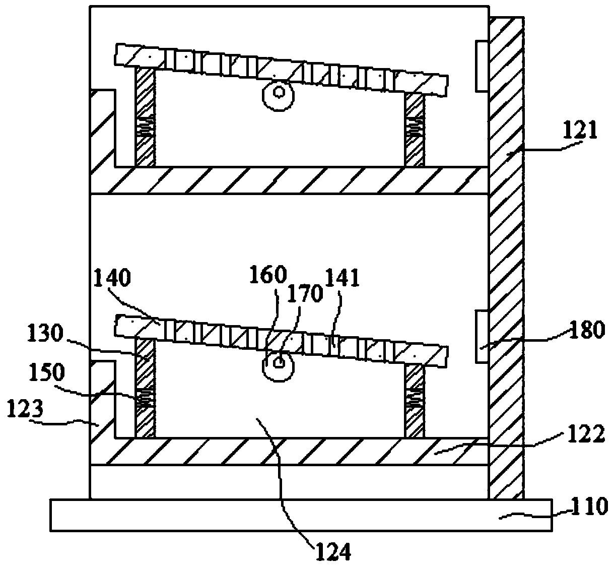
[0122] Such as figure 1 , figure 2 and image 3 As shown, the present embodiment provides a sole cleaning structure of a shoe rack, including a base 110, two parallel side plates 120 and a rear plate 121 are arranged above the base 110, and the rear plate 121 is perpendicular to the side plates 120; A plurality of support plates 122 are sequentially connected between the side plates 120 from bottom to top, one side of the support plates 122 is connected on the back plate 121, and the other side of the support plates 122 is provided with a baffle plate 123 parallel to the back plate 121, the baffle plate 123. The side plates 120 and the rear plate 121 are connected correspondingly and form a dust collection chamber 124 above the support plate 122. A plurality of columns 130 are arranged above the dust collection chamber 124. The tops of all the columns 130 are connected to a the bottom surface of the inclined plate 140 of the shoe;

[0123] Any column 130 is provided with a...

Embodiment 2

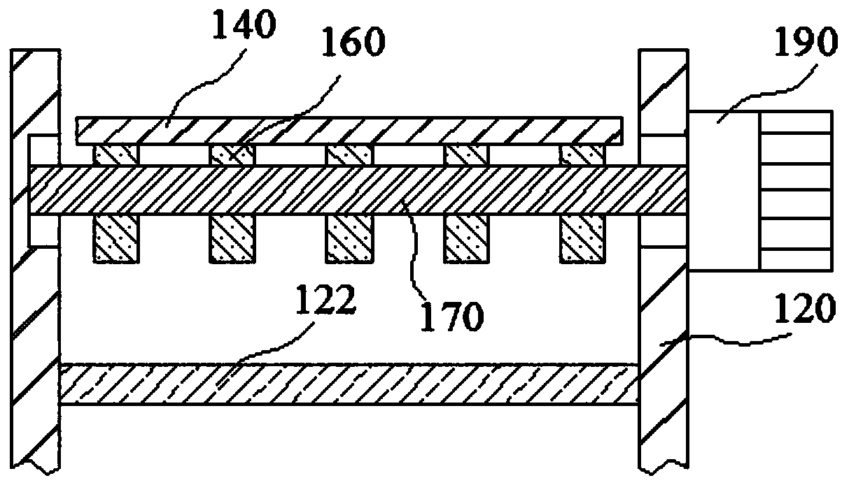
[0136] Such as figure 1 , Figure 4 and Figure 5 As shown, the present embodiment provides a dust removal structure for a shoe rack, including a base 110, two parallel side plates 120 and a rear plate 121 are arranged above the base 110, the rear plate 121 is perpendicular to the side plates 120; A plurality of support plates 122 are sequentially connected between the plates 120 from bottom to top, one side of the support plates 122 is connected on the back plate 121, and the other side of the support plates 122 is provided with a baffle plate 123 parallel to the back plate 121, and the baffle plate 123 1. Corresponding connection between the side plate 120 and the rear plate 121 and a dust collection cavity 124 is formed above the support plate 122. A plurality of columns 130 are arranged above the dust collection cavity 124. The tops of all the columns 130 are connected to a platform for placing shoes. on the bottom surface of the inclined plate 140;

[0137] The support...

Embodiment 3

[0152] Such as figure 1 , Figure 6 , Figure 7 and Figure 8 As shown, the present embodiment provides a deodorizing structure for a shoe rack, including a base 110, two parallel side plates 120 and a rear plate 121 are arranged above the base 110, and the rear plate 121 is perpendicular to the side plates 120; A plurality of support plates 122 are sequentially connected between the side plates 120 from bottom to top, one side of the support plates 122 is connected on the back plate 121, and the other side of the support plates 122 is provided with a baffle plate 123 parallel to the back plate 121, the baffle plate 123. The side plates 120 and the rear plate 121 are connected correspondingly and form a dust collection chamber 124 above the support plate 122. A plurality of columns 130 are arranged above the dust collection chamber 124. The tops of all the columns 130 are connected to a the bottom surface of the inclined plate 140 of the shoe;

[0153] An installation cham...


PUM


Abstract

The invention relates to the technical field of shoe racks, in particular to a multifunctional shoe rack. The multifunctional shoe rack is characterized in that side boards and a rear board are arranged on a base, supporting boards are connected between the side boards, a stop board is arranged on the other sides of the supporting boards to form a dust collecting cavity, vertical columns are arranged above the dust collecting cavity and connected to an oblique board, the supporting board above the oblique board is provided with inclined air spray heads and a mounting cavity, the inclined air spray heads are connected to an air pipe which is connected to a hose, the hose is connected to an air pump, a roller is mounted in the mounting cavity and sleeves one end of a sleeve rod, the other end of the sleeve rod is connected in a threaded cavity positioned in a mounting rod, a transverse rod is arranged below the mounting rod, connecting rods are arranged at two ends of the transverse rod,springs are arranged on the connecting rods, a rubber rod is arranged below the corresponding connecting rod, and a hollow ball is arranged at the lower end of each rubber rod, provided with ventilation holes and filled with deodorants. The multifunctional shoe rack is capable of cleaning shoe surfaces and deodorizing shoes.

Description

technical field [0001] The invention relates to the technical field of shoe racks, in particular to a multifunctional shoe rack. Background technique [0002] When entering a room in a family, for reasons of sanitation, it is often necessary to change shoes, and the shoes changed are often very dirty. If the shoes are cleaned, it will be very troublesome and time-consuming; in addition, the shoes worn by people with smelly feet Putting it on the shoe rack, it smells very bad. Traditional shoe racks can only be used to place shoes, but cannot effectively clean and deodorize shoes. Contents of the invention [0003] In order to overcome some or some defects of the prior art, the present invention provides a shoe sole cleaning structure for a shoe rack. [0004] The sole cleaning structure of the shoe rack according to the present invention comprises a base, two parallel side plates and a rear plate are arranged above the base, the rear plate is perpendicular to the side pl...

Claims


Application Information

Patent Timeline
Patent Type & Authority Applications(China)
IPC IPC(8): A47B61/04A47B96/02A47L23/22A61L2/23A61L101/04
CPCA61L2/23A47B61/04A47B96/025A47L23/22A61L2202/123
Inventor 杨蕊芬
Owner 山东宜和宜美家居科技有限公司
Learn More