Movement-stopping bracket and using method thereof

A bracket and stop technology, applied in brackets and other directions, can solve the problems of unable to lock the arch wire, how to lock the arch wire without details, unable to express the data of the arch wire and bracket well, etc., and achieve high friction force. Effect

Pending Publication Date: 2018-12-28
GUANGZHOU OO MEDICAL SCI LTD
View PDF12 Cites 17 Cited by
  • Summary
  • Abstract
  • Description
  • Claims
  • Application Information

AI Technical Summary

Problems solved by technology

[0003] Prior art 1, Chinese patent application number: 201610264589.5, name: orthodontic bracket system and tooth orthodontic method, which discloses a traction locking element, whose function can perform traction locking as required, but for arch wire There is no detailed technical point on how to lock, and the real archwire locking effect cannot be achieved
[0004] Prior art 2, Chinese patent application number: 201510046931.X, name: traction bracket and orthodontic correction system and its correction method, which discloses a bracket main body with a locking hole and a tra

Method used


Image

  • Movement-stopping bracket and using method thereof
  • Movement-stopping bracket and using method thereof
  • Movement-stopping bracket and using method thereof

Examples


specific Embodiment 1

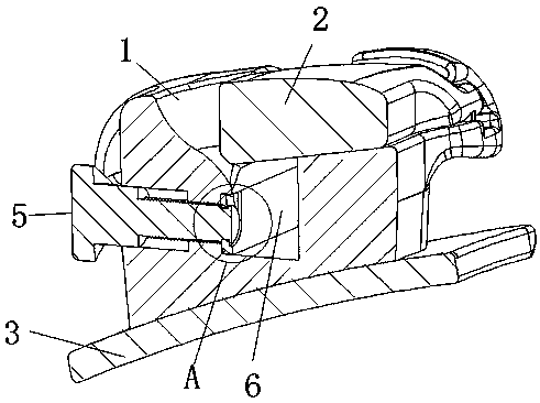
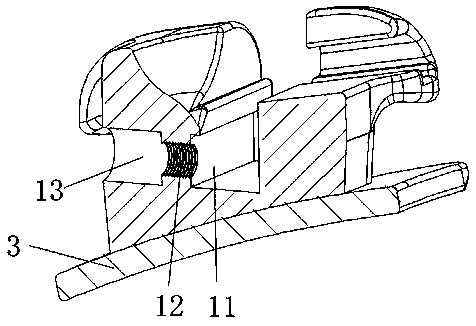
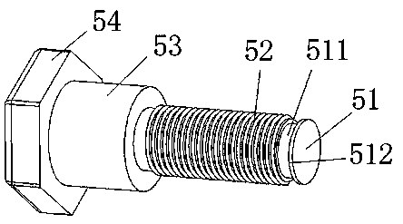
[0055] Such as Figure 1-5 As shown, a stop bracket includes a main body 1, a cover body 2 installed on the main body 1, and a bottom plate 3 installed on the bottom surface of the main body 1, and the main body 1 has a cross The archwire groove, the inner wall of the archwire groove is provided with an adjustment plate avoidance position 11, an adjustment plate 6 is movably installed on the adjustment plate avoidance position 11, the adjustment plate 6 is connected with an adjustment mechanism, and the adjustment mechanism The other end is connected to the main body part 1, and the main body part 1 is provided with a receiving position 12, and the receiving position 12 is connected with the avoiding position 11 of the adjustment plate, and the adjustment mechanism includes a rod-shaped driving rod 5. The receiving position 12 is movably matched with the driving rod 5, and one end of the driving rod 5 is provided with a connecting head 51, and the connecting head 51 is fixedly...

specific Embodiment 2

[0070] Such as Figure 9 and Figure 10 As shown, the difference between this embodiment and Embodiment 1 is:

[0071] It should be noted that the ball bead screw 7 of this embodiment is a prior art, and the internal structure is not drawn in detail in the figure.

[0072] The surface of the connecting section 52 is provided with a track groove 521. The track groove 521 is a straight track or a spiral track. 1. The through hole on the bottom surface, the through hole penetrates to the transition section avoidance position 13, and the ball screw 7 is installed in the through hole. Wherein, the section of the track groove 521 is arc-shaped, and the diameter of the arc is larger than the diameter of the steel ball of the ball screw 7, which is convenient for the steel ball of the ball screw 7 to slide in the track groove. At least one gear groove 522 is provided in the track groove 521, and the ball screw 7 is movably matched with the track groove 521 and the gear groove 522. ...

specific Embodiment 3

[0077] Such as Figure 11 As shown, the differences between this embodiment and Embodiments 1 and 2 are:

[0078] The protruding ring 512 at the end of the connecting head 51 is provided with an inclined surface 513, and the adjusting plate 6 is not penetrated.

[0079] During installation, the inclined surface 513 squeezes the ring groove stop 61, and the ring groove stop 61 expands along the slope 513, so that the convex ring 512 goes over the ring groove stop 61 and enters the convex groove escape position 62. The opposite side of 513 is set as a vertical surface so it is clamped with the ring groove clamping position 61. At this time, the driving rod 5 and the adjusting plate 6 are installed and fixed.

[0080] The advantage of this embodiment is that the fixed connection between the adjusting plate 6 and the driving rod 5 cannot be taken out in reverse, and the structure is more reliable.

[0081] The invention is now described. In use, the invention can drive the adjus...


PUM


Abstract

The invention relates to a bracket for orthodontics and discloses a movement-stopping bracket. The movement-stopping bracket comprises a body part, a cover part installed on the body part and a bottomplate installed on the bottom face of the body part, a transverse through arch wire groove is formed in the body part, an adjusting plate receding position is arranged on the side wall of the arch wire groove, a bearing position is arranged at the adjusting plate receding position, an adjusting plate is movably installed at the adjusting plate receding position and connected with a driving rod, the driving rod is matched with the bearing position, and a connector is arranged at one end of the driving rod and fixedly connected with the adjusting plate. According to the movement-stopping bracket, the size of the arch wire groove can be adjusted, and an arch wire is stopped from moving inside the arch wire groove.

Description

technical field [0001] The invention relates to the field of oral orthodontics, in particular to a bracket used for arch wire stop and its use method. Background technique [0002] The bracket is an important part of orthodontic correction. In the traditional ligation method, the arch wire and the arch wire slot on the bracket are fixed by ligation to realize the data expression of the bracket and the arch wire. Sometimes doctors need to During the correction process, the arch wire is selectively ligated and fixed. [0003] Prior art 1, Chinese patent application number: 201610264589.5, name: orthodontic bracket system and tooth orthodontic method, which discloses a traction locking element, whose function can perform traction locking as required, but for arch wire There is no detailed technical point on how to lock, and the real locking effect of the archwire cannot be achieved. [0004] Prior art 2, Chinese patent application number: 201510046931.X, name: traction bracke...

Claims


Application Information

Patent Timeline
IPC IPC(8): A61C7/14
CPCA61C7/14
Inventor 吉利
Owner GUANGZHOU OO MEDICAL SCI LTD
Why Eureka
Try Eureka