A filter device for pipeline transportation in water conservancy projects

A technology for water conservancy projects and filtration devices, applied in filtration and separation, membrane filters, fixed filter element filters, etc., can solve the problems of time-consuming, labor-intensive, poor filtration effect, and high maintenance costs, and achieve convenient and fast operation, improve service life, Reduce the effect of direct impact

Active Publication Date: 2021-04-09
山东省鲁控科创有限公司
View PDF2 Cites 0 Cited by
  • Summary
  • Abstract
  • Description
  • Claims
  • Application Information

AI Technical Summary

Problems solved by technology

However, the disadvantage of pipeline transportation is that the filtering effect of water is poor, and the garbage in the water is not easy to clean up, and when the existing filter devices on the market are in use, the adjacent filter plates are easily blocked by garbage, and the filter plates will be blocked when cleaning and maintaining the filter plates. Encountered the problem of inconvenient disassembly, time-consuming and laborious, high maintenance costs, very inconvenient to use, affecting work efficiency

Method used


Image

  • A filter device for pipeline transportation in water conservancy projects
  • A filter device for pipeline transportation in water conservancy projects
  • A filter device for pipeline transportation in water conservancy projects

Examples


Embodiment 1

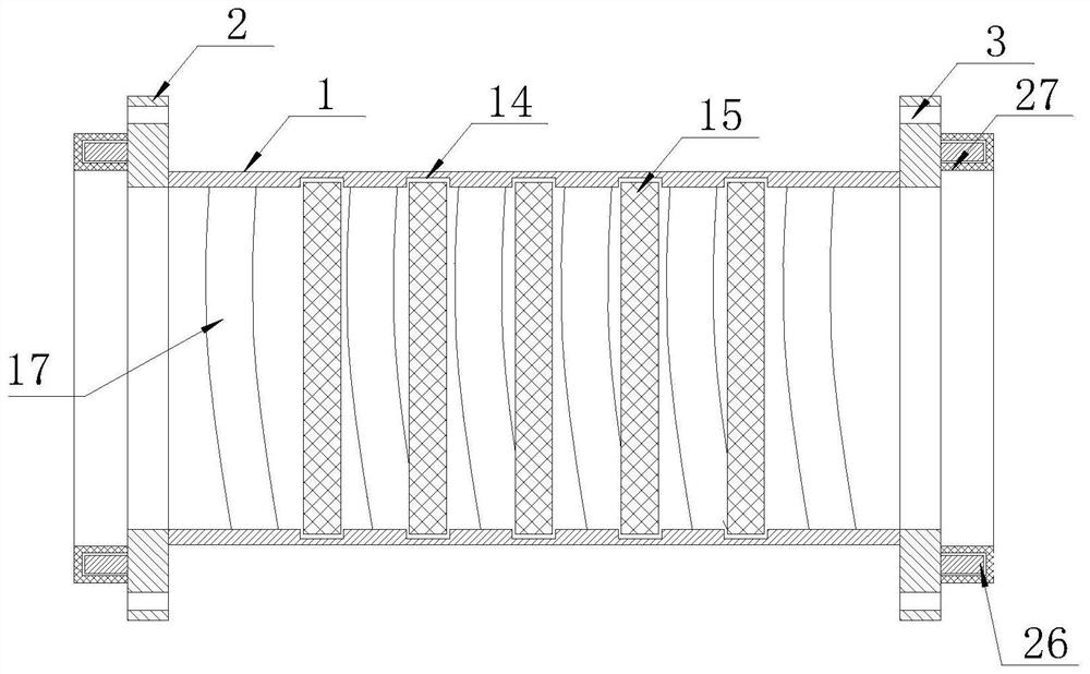
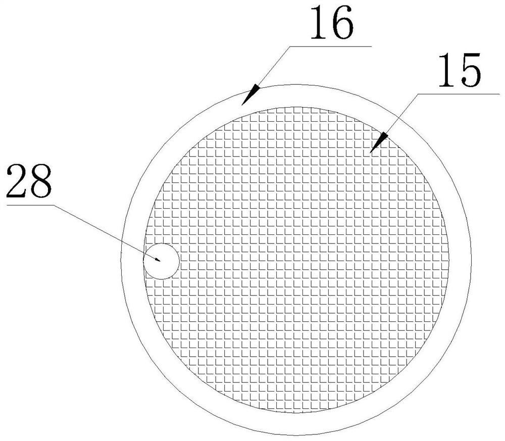
[0032] The present invention provides a filter device for pipeline transportation in water conservancy projects, comprising a filter cavity 1, connecting flanges 2 are arranged at both ends of the filter cavity 1, and positioning Connecting pin holes 3, the filter cavity 1 includes a top cover 101 and a bottom cover 102, both ends of the top cover 101 are fitted with the inner side walls of the connecting flange 2 on the corresponding side, and the two ends of the bottom cover 102 All are fixedly connected with the inner side wall of the connecting flange 2 on the corresponding side, and the inside of the filter chamber 1 is provided with an annular fitting groove 14, and a filter plate 15 is fitted in the annular fitting groove 14, and the edge of the filter plate 15 The position is covered with a sealing rubber ring 16, the inner wall of the filter cavity 1 is provided with a diversion groove 17, the inner side of one end of the bottom cover 102 is provided with a groove 18 a...

Embodiment 2

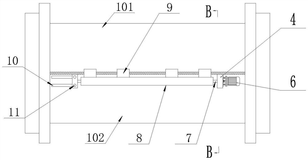
[0038] Further, in the technical solution of Example 1, a slide groove 10 is provided on one end surface of the bottom cover 102, and a threaded hole is provided at the bottom end of the slide groove 10, and the bottom end of one of the first fixing blocks 4 is arranged on In the chute 10, and movably connected with the chute 10, the top of one of the first fixed blocks 4 is provided with a first locking screw hole 11, and the first locking screw hole 11 matches the threaded hole , the outer fixed sleeve of the rotating shaft 7 is provided with a transmission gear 12, the inner wall of the sleeve 8 is equipped with gear teeth 13, the transmission gear 12 is meshed with the gear teeth 13, and both ends of the sleeve 8 are connected to the opposite side. The inner wall of the first fixed block 4 of the filter cavity 1 is attached to the inner wall. When the top cover 101 or the bottom cover 102 of the filter chamber 1 is partially damaged, the connecting flange 2 on the side away...


PUM


Abstract

The invention discloses a filter device used for pipeline transportation in water conservancy projects, comprising a filter cavity, a filter plate and a turning mechanism, the filter cavity includes a bottom cover and a top cover, the bottom cover is provided with a fixed block, the The top cover is provided with a connecting block; an annular fitting groove is arranged in the filter cavity, and the filter plate is fitted in the annular fitting groove; the turning mechanism includes a servo motor, a rotating shaft and a sleeve, and the rotating shaft It is arranged between the fixed blocks, the rotating shaft is sleeved in the sleeve, the outer wall of the sleeve is fixedly connected with the connecting block, and the output shaft of the servo motor is connected with the rotating shaft. The invention drives the shaft to rotate through the servo motor, and then drives the sleeve to rotate, thereby driving the top cover to turn over, which facilitates the replacement and maintenance of the filter plate. At the same time, the shaft can be pulled out in the sleeve to facilitate the replacement of the top cover and the bottom cover, which is simple and easy. Low maintenance cost.

Description

technical field [0001] The invention relates to the technical field of water conservancy engineering, in particular to a filtering device used for pipeline transportation in water conservancy engineering. Background technique [0002] Water is a precious resource for human survival, but its natural state does not fully meet the needs of human beings. Only by building water conservancy projects can water flow be controlled, floods prevented, and water volume adjusted and distributed to meet the needs of people's lives and Production needs water resources, and water conservancy projects need to build different types of hydraulic structures such as dams, dikes, spillways, sluices, water inlets, channels, crossings, rafts, and fishways to achieve their goals. In the process of water transportation, pipeline transportation is often adopted in order to reduce the loss of water resources. However, the disadvantage of pipeline transportation is that the filtering effect of water is...

Claims


Application Information

Patent Timeline
Patent Type & Authority Patents(China)
IPC IPC(8): B01D29/58B01D29/62
CPCB01D29/58B01D29/62B01D2201/301
Inventor 侯德国王亮李睿骐张寒冰
Owner 山东省鲁控科创有限公司
Why Eureka
Try Eureka