Supercharge Your Innovation With Domain-Expert AI Agents!

Glass kiln gas denitration spray ammonia injection grid online ash removing device and ash removing method thereof

A technology for ammonia spraying grids and glass furnaces, applied in separation methods, chemical instruments and methods, furnaces, etc., can solve problems such as manual cleaning of flue dust, burial of ammonia spraying grid dust accumulation, ammonia spraying grid coverage, etc. , to achieve long-term stable operation, avoid the risk of dust accumulation in the flue, and ensure the effect of kiln pressure

Active Publication Date: 2018-12-28
湖南旗滨光能科技有限公司
View PDF13 Cites 1 Cited by
  • Summary
  • Abstract
  • Description
  • Claims
  • Application Information

AI Technical Summary

Problems solved by technology

[0007] The present invention aims to solve the problem that during the long-term use of the existing float glass environmental protection system denitrification process, these flue ash cannot be manually cleaned, and the flue ash brought by the flue gas of the melting furnace gradually accumulates in the flue, which is easy to cause damage to the flue. Covering the ammonia spraying grid; the ammonia spraying grid is buried by ash accumulation, which leads to the problem of high resistance of the environmental protection system and poor ammonia spraying effect, and provides an online ash cleaning device for glass kiln flue gas denitrification ammonia spraying grid and Its cleaning method, in the environmental protection operation, under the condition of ensuring the stability of the kiln pressure, realizes the online ammonia spray grid dust cleaning, avoids the risk of dust accumulation in the flue, and realizes the long-term stable operation of the overall environmental protection system

Method used


Image

  • Glass kiln gas denitration spray ammonia injection grid online ash removing device and ash removing method thereof
  • Glass kiln gas denitration spray ammonia injection grid online ash removing device and ash removing method thereof
  • Glass kiln gas denitration spray ammonia injection grid online ash removing device and ash removing method thereof

Examples


Embodiment 1

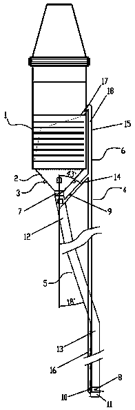
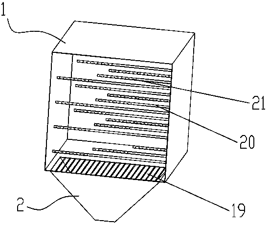
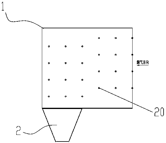
[0039] exist figure 1 , figure 2 In the shown embodiment, an online ash cleaning device for glass kiln flue gas denitrification and ammonia injection grid includes:

[0040] Ammonia injection grid 1, a device for injecting ammonia;

[0041] Ash hopper device 2, ash hopper device 2 is arranged under ammonia spray grid 1 and communicated with ammonia spray grid 1; ash hopper device 2 is provided with vibration device 3;

[0042] The circulation channel 4 is used to realize the communication and circulation of flue gas; the circulation channel 4 communicates with the ammonia injection grid 1 and the ash hopper device 2 respectively through the control valve, and forms the internal circulation of the flue gas and the flue ash under the pressure maintaining state.

[0043] Circulation channel 4 includes ash lowering pipeline 5 and communication pipeline 6 which communicate with each other; the control valve includes: ash lowering electric magnetic valve 7 set on the upper end of...


PUM


Abstract

The invention discloses a glass kiln gas denitration spray ammonia injection grid online ash removing device. The device comprises an ammonia injection grid for injecting ammonia; a hopper device arranged under the ammonia injection grid and communicated with the ammonia injection grid, wherein the hopper device is provided with a vibrating device; a circulation passage used for achieving gas communication cycle, wherein the circulation passage is respectively communicated with the ammonia injection grid and the hopper device through control valves and form the gas and flue ash inner cycle inthe pressure maintaining state. A method for online ash removing by using the glass kiln gas denitration spray ammonia injection grid online ash removing device is also disclosed. The device ensures the stability of the kiln pressure due to achievement of the gas inner cycle in the environmental protection operation, achieves the effective ash removing of the online ammonia injection grid, and avoids the risk of flue ash accumulation, achieves long-term stable operation of the overall environmental protection system and greatly reduces production and maintenance costs.

Description

technical field [0001] The invention relates to the technical field of denitrification process of float glass environmental protection system, and more specifically relates to an online ash removal device and a method for denitrification of flue gas in a glass kiln and an ammonia injection grid. Background technique [0002] At present, the denitrification process of the float glass environmental protection system adopts the selective catalytic reduction method (SCR). This reaction occurs in a reactor equipped with a catalyst. removal. During long-term use, the flue ash brought by the flue gas of the melting furnace gradually accumulates in the flue, which is likely to cause coverage of the ammonia injection grille; during routine maintenance, it was found that the ash accumulation at the ammonia injection grille of the second line exceeded the flue 70% of the cross-section, the ammonia injection grid is completely buried by ash, resulting in high system resistance and poor...

Claims


Application Information

Patent Timeline
Patent Type & Authority Applications(China)
IPC IPC(8): B01D53/90B01D53/56F27D17/00F23J1/06
CPCB01D53/8631B01D53/90B01D2251/2062B01D2258/0283F23J1/06F27D17/00
Inventor 杨雷訚清张青
Owner 湖南旗滨光能科技有限公司
Features
  • R&D
  • Intellectual Property
  • Life Sciences
  • Materials
  • Tech Scout
  • Unparalleled Data Quality
  • Higher Quality Content
  • 60% Fewer Hallucinations
Learn More