Online surface cleaning monitoring and treatment device and method for optical element

A technology for optical components and processing devices, applied to chemical instruments and methods, cleaning methods using tools, cleaning methods and appliances, etc., can solve problems such as surface damage, time-consuming, labor-intensive, and damage of optical components, and ensure stable operation , Avoid secondary pollution, simple and convenient operation

Pending Publication Date: 2018-12-28
LASER FUSION RES CENT CHINA ACAD OF ENG PHYSICS
View PDF17 Cites 4 Cited by
  • Summary
  • Abstract
  • Description
  • Claims
  • Application Information

AI Technical Summary

Problems solved by technology

According to the actual situation of device operation and maintenance, we found that the surface of the large-aperture mirror installed obliquely upward at 45° often has dust deposition phenomenon, which is damaged and gradually increased under the action of strong laser light, which eventually leads to the failure of normal use of the components, which greatly affects High-throughput and stable operation of the device
In the process of operation and maintenance, although we have carried out clean tracking and control on the clean cleaning, precision assembly, cross-regional transfer and on-site installation of mechanical and optical components, so that the surface cleanliness of the components before they are put on the shelves meets the requirements of the specifications, and at the same time During the operation and maintenance process, the surface of the optical element was kept clean by means of unpacking inspection and manual wiping, but it was still found that the surface of the optical element was damaged during the operation of the device. Through analysis, it was found that although unpacking inspection and manual wiping can alleviate the damage to a certain extent The degree of cleanliness and cracking of the surface of the optical element, but the human operation also brings the risk of secondary pollution to the optical element and the optical transmission pipeline. At the same time, this time-consuming and labor-intensive work cannot realize real-time monitoring and real-time It is not a good choice for daily cleaning and maintenance of mirrors

Method used


Image

  • Online surface cleaning monitoring and treatment device and method for optical element
  • Online surface cleaning monitoring and treatment device and method for optical element
  • Online surface cleaning monitoring and treatment device and method for optical element

Examples


Embodiment Construction

[0031] The present invention will be further described in detail below in conjunction with the accompanying drawings, so that those skilled in the art can implement it with reference to the description.

[0032] It should be understood that terms such as "having", "comprising" and "including" as used herein do not entail the presence or addition of one or more other elements or combinations thereof.

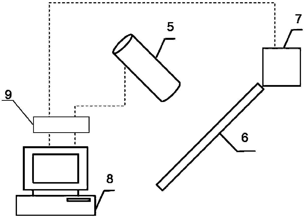
[0033] figure 1 An apparatus for on-line surface cleaning monitoring and treatment of optical components is shown, comprising:

[0034] The online detection system for particles on the surface of the optical element, the dark field imaging system 5 is located above the optical element 6 and perpendicular to the optical element 6;

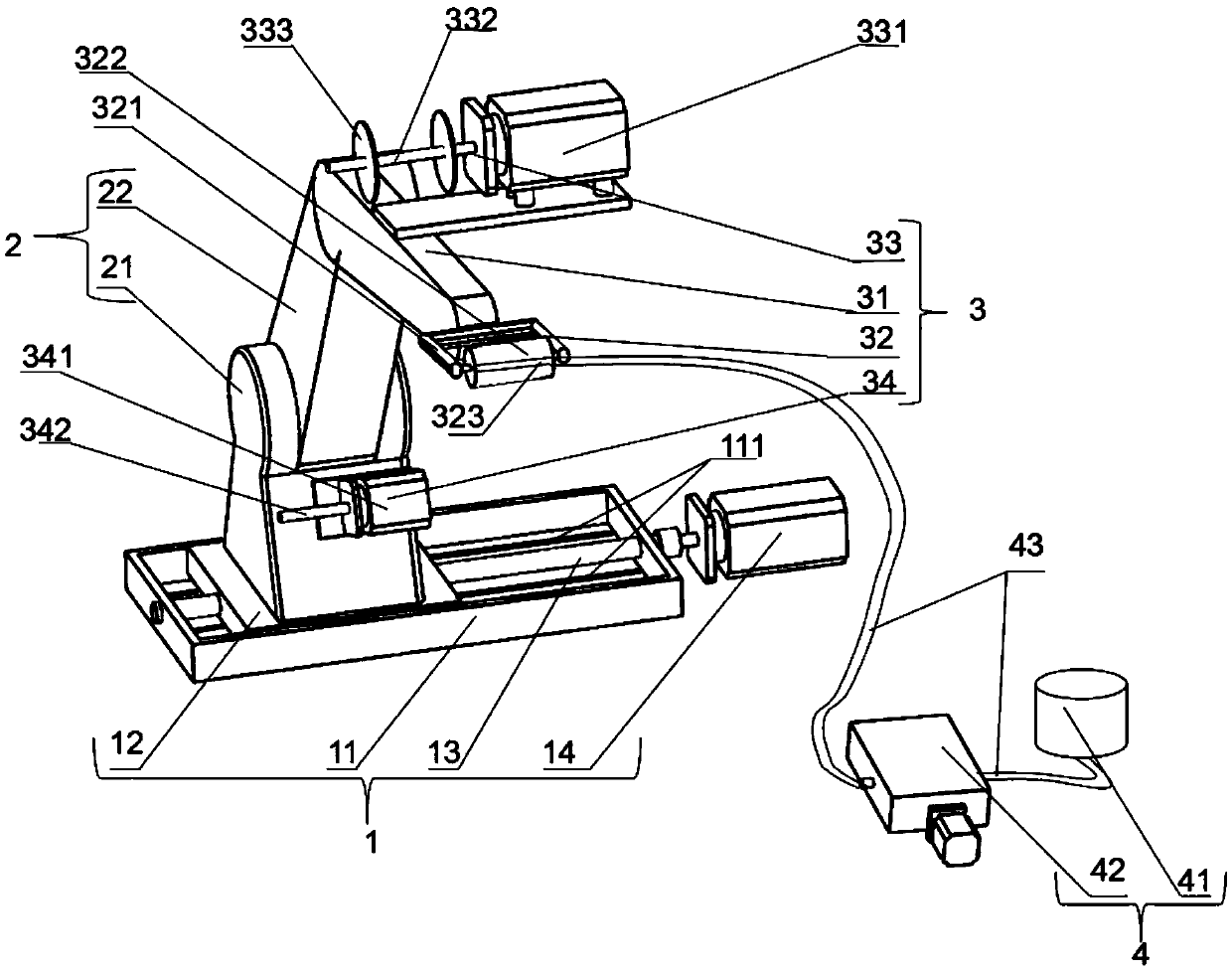
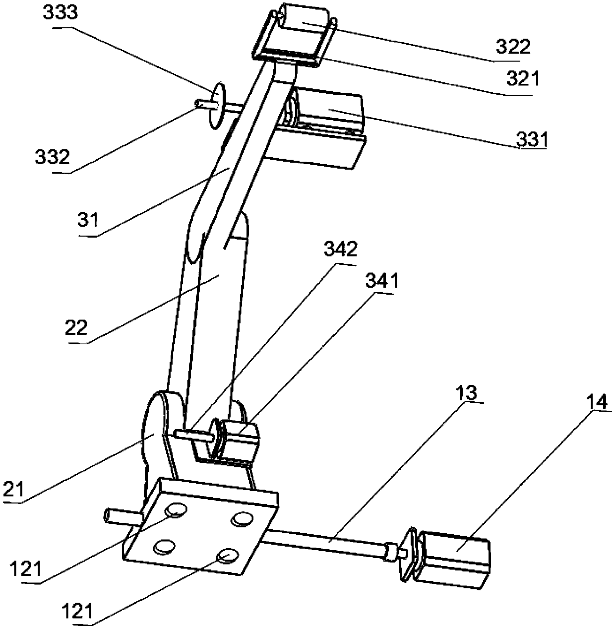
[0035] A cleaning treatment device 7 for cleaning the optical elements, which moves the position of the wiping mechanism 32 through the horizontal movement mechanism 1 and the vertical telescopic mechanism 2, and then can wipe the surface of the optic...


PUM


Abstract

The invention discloses an online surface cleaning monitoring and treatment device and method for an optical element. The device comprises an optical element surface particulate matter online detection system, a dark field imaging system of which is located above the optical element and is perpendicular to the optical element; a cleaning treatment device, used for cleaning the optical element andcapable of realizing location moving of a wiping mechanism through a horizontal motion mechanism and a vertical telescopic mechanism, so as to wipe the surface of the optical element; and an upper computer, connected with the optical element surface particulate matter online detection system and the cleaning treatment mechanism in a communication manner. The device and the method which are disclosed by the invention can be applied to real-time online monitoring of the surface of the optical element and clean the surface in time according to a result monitored by a dark field, is easy and convenient to operate, and avoids the risk of secondary pollution caused by manual work, thus reducing damage to the optical element and effectively guaranteeing stable operation of a high-power solid laser device.

Description

technical field [0001] The invention belongs to the field of cleaning control of optical components, and in particular relates to a device and method for online surface cleaning monitoring and processing of optical components. Background technique [0002] The construction of high-power solid-state laser devices requires a huge number and variety of optical components. Taking NIF as an example, the whole device contains 7460 large-aperture optical components (0.5-1.0m), making it not only the largest laser in the world, but also the largest optical system ever. Under the high-flux operating conditions of the laser device, the particle contamination on the surface of the optical element will induce damage under the action of strong laser light, which is the main factor leading to local damage. Therefore, removing particle contamination on the surface of optical components is an effective measure to ensure the safe use of components and maintain the high-throughput and stable...

Claims


Application Information

Patent Timeline
Patent Type & Authority Applications(China)
IPC IPC(8): B08B1/00B08B13/00
CPCB08B1/006B08B1/008B08B13/00
Inventor 蒋一岚苗心向贾宝申吕海兵周国瑞牛龙飞刘昊马志强邹睿刘青安姚彩珍蒋晓东周海
Owner LASER FUSION RES CENT CHINA ACAD OF ENG PHYSICS
Why Eureka
Try Eureka